Eureka AIR delivers breakthrough ideas for toughest innovation challenges, trusted by R&D personnel around the world.

Article conveyance apparatus

Pending Publication Date: 2022-05-26
DAIFUKU CO LTD
View PDF0 Cites 0 Cited by
  • Summary
  • Abstract
  • Description
  • Claims
  • Application Information

AI Technical Summary

Benefits of technology

The article conveyance apparatus described in this patent text uses a measuring unit in each conveyor carriage to calculate the tension between conveyor carriages in real-time. This means that any issues with the tension between carriages can be quickly detected and addressed, without having to stop the conveyor. The apparatus also predicts when the wheels may start to float from the surface they are traveling on, which prevents this from happening. These technical effects improve operational efficiency and make the conveyor run more smoothly.

Problems solved by technology

In the conventional article conveyance apparatus, unfortunately, the tension between the conveyor carriages can be detected only when the conveyor carriages are stopped, requiring the all conveyor carriages to be stopped each time the tension between the conveyor carriages is detected.
This may cause low operation efficiency.
Furthermore, in the conventional article conveyance apparatus, whether the wheels are floating from the traveling surface is determined by detecting the tension between the conveyor carriages, however, the tension between the conveyor carriages cannot be detected during the travel of the conveyor carriages, so that floating of the wheels from the traveling surface cannot be determined during the travel of the conveyor carriages.
Thus, the wheels cannot be prevented from floating from the traveling surface.

Method used


Image

  • Article conveyance apparatus
  • Article conveyance apparatus
  • Article conveyance apparatus

Examples


Embodiment Construction

[0025]An article conveyance apparatus 10 according to an embodiment of the present invention will be described below.

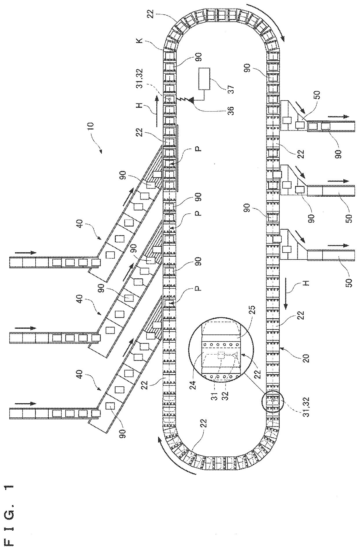
[0026]As illustrated in FIG. 1, a loop conveyance path K is formed in the article conveyance apparatus 10. The article conveyance apparatus 10 mainly includes a main conveyor device 20 for conveying articles 90 along the conveyance path K, a plurality of induction conveyors 40 for loading the articles 90 onto the conveyance path K of the main conveyor device 20, and a plurality of chutes 50 for receiving the articles 90 unloaded from the conveyance path K of the main conveyor device 20. In the article conveyance apparatus 10, the articles 90 are loaded onto the conveyance path K of the main conveyor device 20 from the predetermined induction conveyors 40. The articles90 to be loaded onto the conveyance path K are received at article-loading positions P by the main conveyor device 20. The articles 90 are conveyed by conveyor carriages 22 traveling on the conveyance pat...


PUM


Abstract

An article conveyance apparatus couples a plurality of conveyor carriages for conveying articles and enables the coupled conveyor carriages to travel along a conveyance path K. The conveyor carriage is coupled by a coupling part to another conveyor carriage placed in the longitudinal direction with respect to a traveling direction H of the conveyor carriage. The conveyor carriage includes a load cell that is provided in the coupling part and measures a force applied between the conveyor carriages, and a controller that calculates a force F applied to wheels of the conveyor carriage, based on a tension T between the conveyor carriages calculated according to the force applied between the conveyor carriages and measured by the load cell.

Description

FIELD OF THE INVENTION[0001]The present invention relates to an article conveyance apparatus that couples a plurality of conveyor carriages for conveying articles and enables the coupled conveyor carriages to travel along a conveyance path.BACKGROUND OF THE INVENTION[0002]As a conventional article conveyance apparatus of this type, an article conveyance apparatus described in Japanese Patent Laid-Open No. 2005-255331 is available, for example.[0003]The article conveyance apparatus described in Japanese Patent Laid-Open No. 2005-255331 includes a plurality of conveyor carriages that move along rails. The conveyor carriages adjacent to each other in a moving direction are coupled to each other by a coupling part. In the article conveyance apparatus described in Japanese Patent Laid-Open No. 2005-255331, the conveyor carriages are moved along the loop rails. When the conveyor carriages reach desired sorting positions, articles on the conveyor carriages are sorted to the sorting positio...

Claims


Application Information

Patent Timeline
IPC IPC(8): B61B13/00B65G47/46B65G17/34G01L5/00
CPCB61B13/00B65G47/46B65G2203/0266G01L5/00B65G17/345B65G47/96B65G2203/042B65G23/02B61G7/00B61D49/00B65G35/06
Inventor UEDA, YUICHIMATSUI, OSAMUKOIDE, HIROYUKIISHIKURA, ATSUSHI
Owner DAIFUKU CO LTD
Why Eureka
Eureka Blog
Learn More