Power switch circuit with current sensing
- Summary
- Abstract
- Description
- Claims
- Application Information
AI Technical Summary
Benefits of technology
Problems solved by technology
Method used
Image

Examples
Embodiment Construction
[0021]Reference will now be made in detail to the exemplary embodiments, the same or similar reference numbers or components used in the drawings and the embodiments are used to represent the same or similar parts.
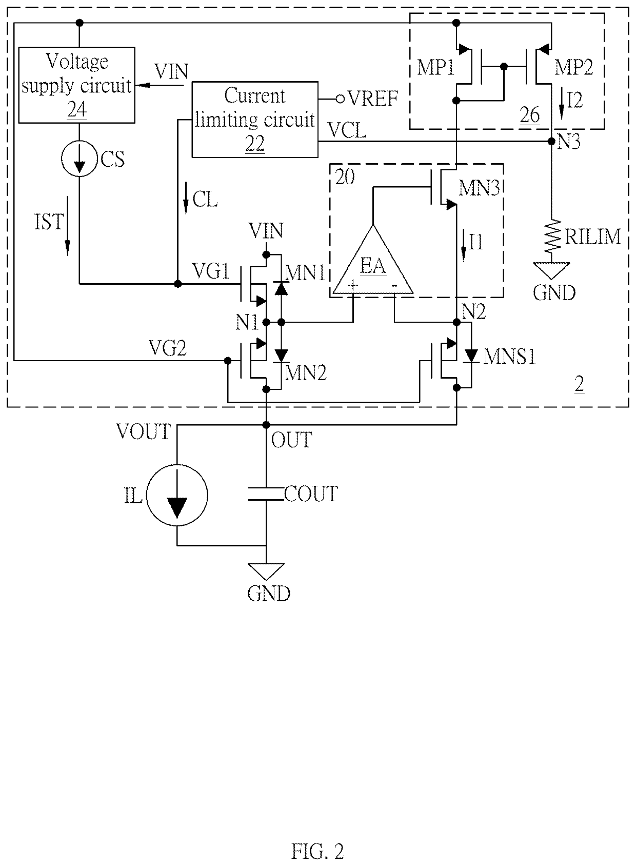
[0022]An embodiment of the invention is a power switch circuit with current sensing. Please refer to FIG. 2. FIG. 2 is a schematic diagram of the power switch circuit with current sensing in this embodiment.
[0023]As shown in FIG. 2, the power switch circuit 2 is coupled between an input voltage VIN and an output terminal OUT. The output terminal OUT is coupled to one terminal of an output capacitor CL and the other terminal of the output capacitor CL is coupled to a ground terminal GND. The output terminal OUT has an output voltage VOUT and an output current IL flows from the output terminal OUT to the ground terminal GND.
[0024]The power switch circuit 2 includes a power switch MN1, a first sensing switch MN2, a second sensing switch MNS1, an adjusting circuit 20, a curren...
PUM
 Abstract
Description
Claims
Application Information
 - Generate Ideas
- Intellectual Property
- Life Sciences
- Materials
- Tech Scout
- Unparalleled Data Quality
- Higher Quality Content
- 60% Fewer Hallucinations
Browse by: Latest US Patents, China's latest patents, Technical Efficacy Thesaurus, Application Domain, Technology Topic, Popular Technical Reports.
© 2025 PatSnap. All rights reserved.Legal|Privacy policy|Modern Slavery Act Transparency Statement|Sitemap|About US| Contact US: help@patsnap.com