
Bi-Directional Oxygenation Apparatus for a Non-Intubated Patient

a non-intubated patient and oxygenation technology, applied in the field of medical equipment, can solve the problems of undesirable intubation, dangerously distressed patients, and inability to inhale or exhale on his own, and achieve the effects of increasing oxygen, increasing the amount of oxygen, and reducing the airflow of exhalation

Inactive Publication Date: 2022-06-02
BOUTROS M D F A C S SEAN +1
View PDF0 Cites 1 Cited by
  • Summary
  • Abstract
  • Description
  • Claims
  • Application Information

AI Technical Summary

Benefits of technology

The present invention is a self-administered oxygenation apparatus that helps increase the amount of oxygen in a patient's blood when operated. The apparatus includes a mouthpiece, a vent member, and a resistance member. The resistance member is positioned between the interior area of the vent member and the mouthpiece, and is operable to move pivotally between an open configuration and a closed configuration. When in the open configuration, ambient air inhaled by the patient passes through without resistance. When in the closed configuration, the resistance member blocks a portion of exhaled air, reducing the airflow and increasing the pressure inside the airway. The apparatus also provides resistance to exhaled air, expanding the patient's airway and improving oxygenation of the blood. Additionally, the resistance member can be moved to decrease the flow of air that is passing outwardly during exhalation. These features make the apparatus effective in improving oxygenation and respiratory function in patients, even without the need for intubation.

Problems solved by technology

The patient in such cases may be unable to inhale or exhale on his own, or at least efficiently.
Although presumably effective for its intended use, the current method of treating a dangerously distressed patient with a full ventilator and intubated patient is undesirable for a patient that is not intubated and not being treated on a full ventilator setup.

Method used


Image

  • Bi-Directional Oxygenation Apparatus for a Non-Intubated Patient
  • Bi-Directional Oxygenation Apparatus for a Non-Intubated Patient
  • Bi-Directional Oxygenation Apparatus for a Non-Intubated Patient

Examples


Embodiment Construction

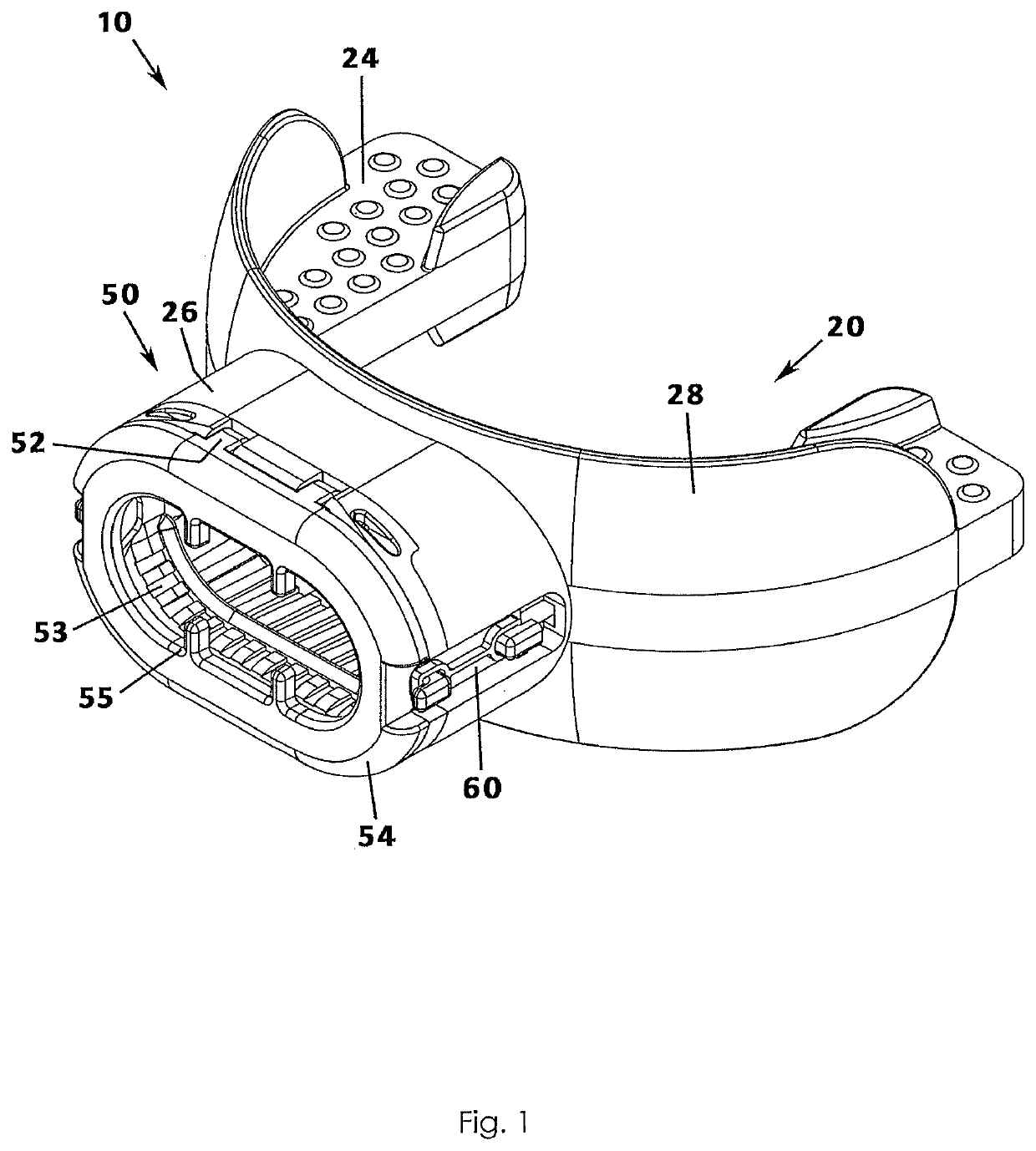
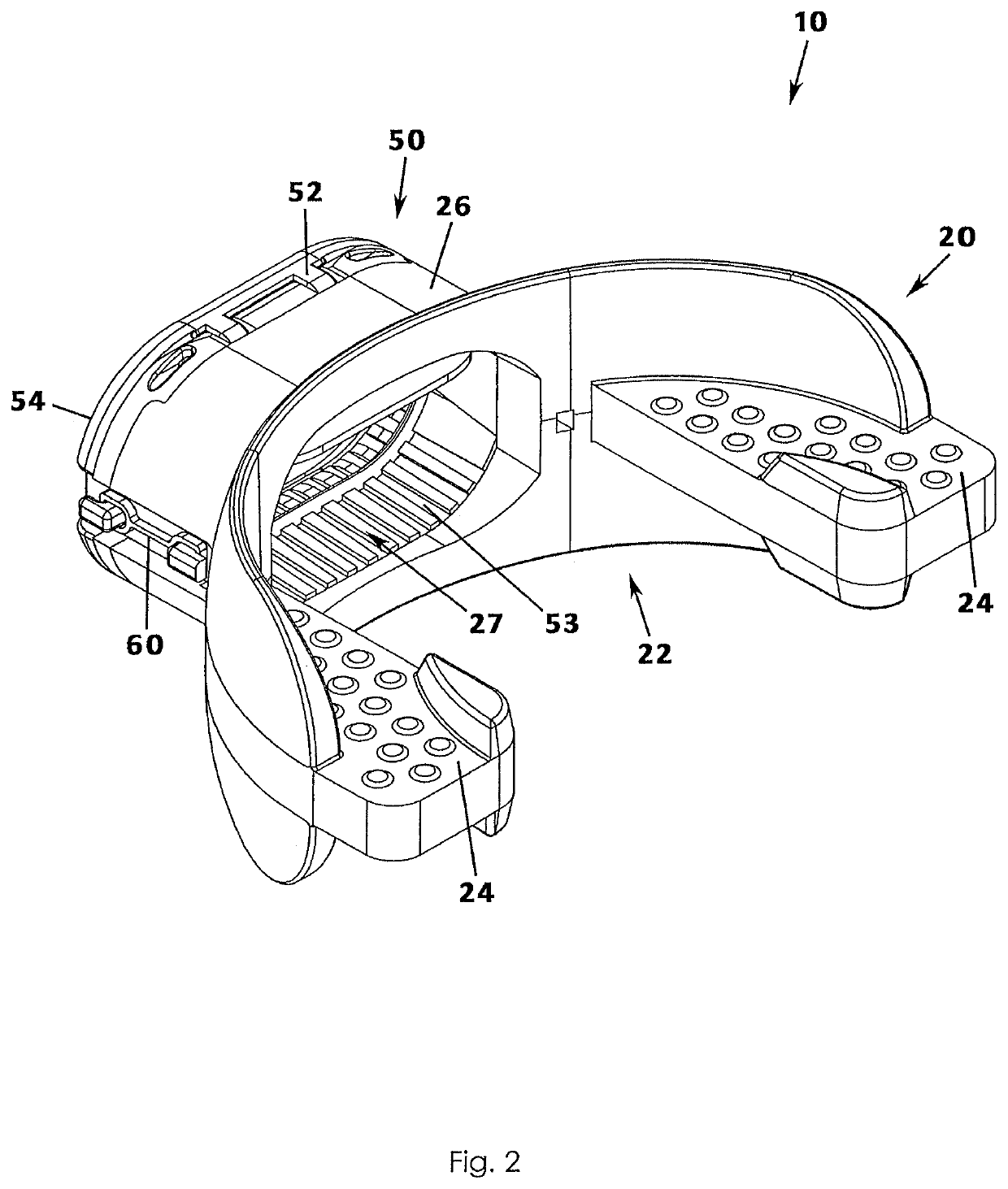
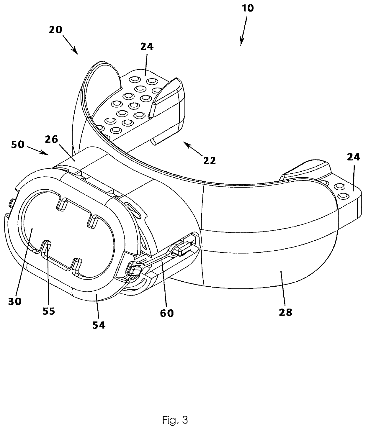
[0051]A bi-directional oxygenation apparatus for a patient according to a preferred embodiment will now be described with reference to FIGS. 1 to 28 of the accompanying drawings. The bi-directional oxygenation apparatus 10 includes a mouthpiece 20 having an external portion 26, a resistance member 30 for regulating inhalation and exhalation resistance, and a vent member 50. As will be described in greater detail later, the vent member 50 may also be referred to as a vent port through which ambient air is inhaled into the device and inhaled air is exhaled, a portion of which may be analyzed by integrated medical sensors. It will be understood that references to a “patient” herein also contemplates users not under the care of any doctor and, therefore, not a typical ‘patient,” such as an athlete using the oxygenation apparatus 10 while practicing or while engaged in game play.

[0052]It is understood that references herein to a patient refer to a patient who is not intubated or being tr...


PUM


Abstract

A self-administered oxygenation apparatus for increasing pressure within a non-intubated patient's lungs and thereby increasing an amount of oxygen in the non-intubated patient's blood when operated by the patient includes a mouthpiece, a vent member, a resistance member, and a plurality of medical sensors. The medical sensors are configured to receive a portion of the exhalation and to transmit generated medical data to a remote location, such as to a software application via the internet. The mouthpiece includes an external portion through which the patient inhales and exhales. The resistance member is a PEEP valve configured to open upon inhalation so as to allow ambient air inhaled by the patient to pass thereby without resistance and to close upon exhalation, exhalation causing an end shield to pivot outwardly from the vent member under a bias of external elastic members.

Description

REFERENCE TO RELATED APPLICATIONS[0001]This application claims the priority of provisional patent application 63 / 119,784, filed Dec. 1, 2020 titled Bi-Directional Oxygenation Apparatus for a Non-Intubated Patient which is related to non-provisional patent application Ser. No. 16 / 367,887 filed Mar. 28, 2019 titled Bi-Directional Oxygenation Apparatus for a Non-Intubated Patient (now U.S. Pat. No. 10,463,912), which claims the benefit of non-provisional patent application Ser. No. 15 / 837,532 filed Dec. 11, 2017 titled Bi-Directional Oxygenation Apparatus for a Non-Intubated Patient (now U.S. Pat. No. 10,252,021), which claims the benefit of U.S. Ser. No. 15 / 672,530 filed Aug. 9, 2017 titled, Bi-Directional Oxygenation Apparatus for a Non-Intubated Patient (now U.S. Pat. No. 10,080,511) all of which are incorporated in their entirety herein by reference.BACKGROUND OF THE INVENTION[0002]This invention relates generally to medical equipment intended to increase oxygenation of the blood o...

Claims


Application Information

Patent Timeline
Patent Type & Authority Applications(United States)
IPC IPC(8): A63B23/18A61M16/04A61M16/20
CPCA63B23/18A61M16/208A61M16/0488A61M2205/3553A61M2205/3592A61M2205/505G16H20/40A61M16/0493A61M2202/0225A61M16/0866A61M2205/0216A61M16/205A61M16/20A61M16/0808A61M2230/435A61M2230/432A61M2230/06A61M2230/205A61M2205/3306A61M2205/3375A61M2209/088A61M2205/3561A61M2205/52A61M2205/8206A61M2230/437A61M2202/0233G16H40/63G16H40/67A61B5/4836A61B5/082A61B5/0205A61B5/14542A61M2202/0085
Inventor BOUTROS, M.D., F.A.C.S., SEANBENTON, WILLIAM
Owner BOUTROS M D F A C S SEAN
Learn More