System and method for location determination and robot control

a robot and location technology, applied in the field of system and method for location determination and robot control, can solve the problems of increasing costs, inefficiency, robots will be unable to retrieve objects,

Pending Publication Date: 2022-06-02
MASSACHUSETTS INST OF TECH
View PDF0 Cites 1 Cited by
  • Summary
  • Abstract
  • Description
  • Claims
  • Application Information

AI Technical Summary

Benefits of technology

[0016]In embodiments learning the one or more policies includes implementing a spatio-temporal reward function. In embodiments, the reward function is implemented as an inverse of a distance from a location of the RF-tagged object, the reward maximized for earlier success corresponding to a temporal part of the spatio-temporal reward function.
[0017]In embodiments, the one or more policies correspond to directly grasping the RF-tagged object.
[0018]In embodiments the one or more policies include: performing decluttering prior to controlling the robot to grasp the RF-tagged object.
[0019]In embodiments, the decluttering includes extracting one or more occluded objects from a pile.
[0020]In embodiments the decluttering includes moving one or more occluded objects or moving one or more distractor items to a side location.
[0021]In accordance with a further aspect of the concepts describes herein, a control system, comprises a storage area configured to store instructions; and a controller configured execute the instructions to: a) determine a location of a tagged target object in an area of interest based on a radio frequency (RF) signal, b) determine a trajectory to grasp the tagged target object based on a combination of the RF frequency signal and visual information from a vision sensor; and c) generate a control signal to perform a robot grasping operation which includes picking up the tagged target object along a line-of-sight relative to a robot in a state where the tagged target object is not partially or fully occluded.

Problems solved by technology

As a result, the robot will be unable to retrieve the object, thus necessitating intervention of a human worker to resolve the problem.
This introduces inefficiencies and increases costs.
Without direct line-of-sight (i.e. in partially or fully occluded environments), existing systems are unable to retrieve target objects.
Moreover, existing systems are typically limited for use in a single pile or pick-up bin, not for locating and / or retrieving objects in multiple piles or objects which are occluded from view by multiple obstacles disposed over them.

Method used


Image

  • System and method for location determination and robot control
  • System and method for location determination and robot control
  • System and method for location determination and robot control

Examples


example implementation

[0154]One example implementation of the system may include a UR5e robot arm, 2F-85 Robotiq gripper, and an Intel Real-Sense D415 depth camera mounted on the gripper. The RF perception module is implemented as an RFID localization system on USRP software radios. The RFID localization system may be set up on a table in front of the robot arm 16 cm, at a position below the robot base level. The robot may be connected through Ethernet to a PC that runs Ubuntu 16.04 and may have an Intel Core i9-9900K processor; RTX 2080 Ti, 11 GB graphic card; and 32 GB RAM. A USB to RS485 interface to control the gripper from the PC.

[0155]The robot may be controlled using Universal Robots ROS Driver on ROS kinetic. Moveit! software and OMPL for planning scene and inverse kinematic solver may also be used. TSDF volume may be created using Yak, and PCL may be used to extract clusters and occlusion from TSDF volume. To solve the SQP for trajectory optimization, FORCES may be used. Code for the instruction...


PUM


Abstract

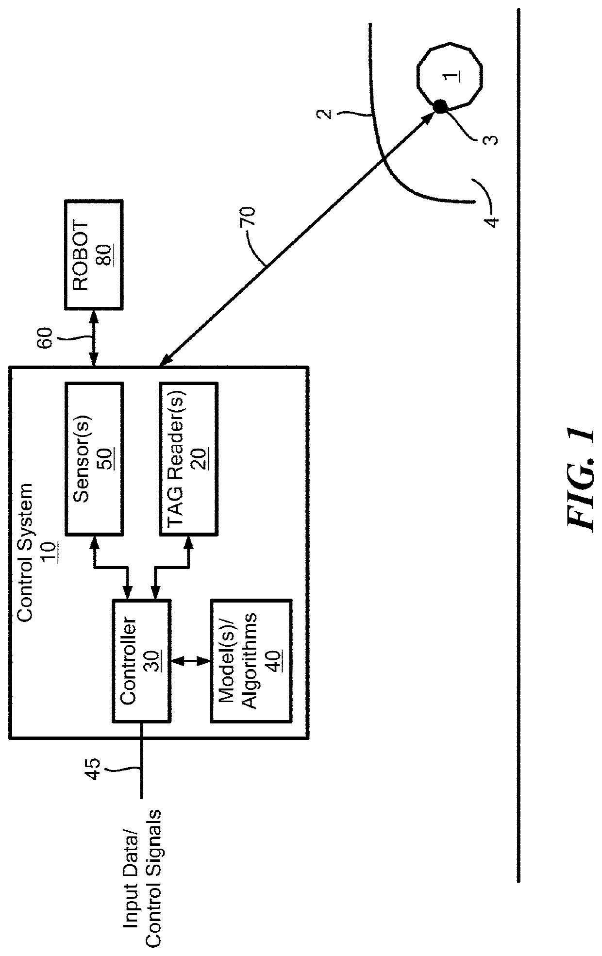
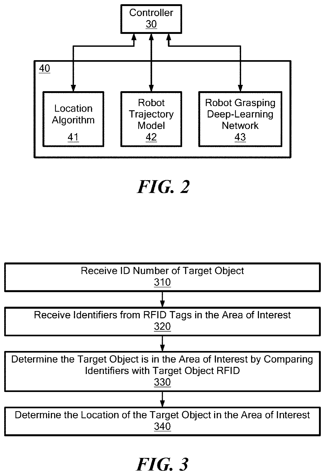
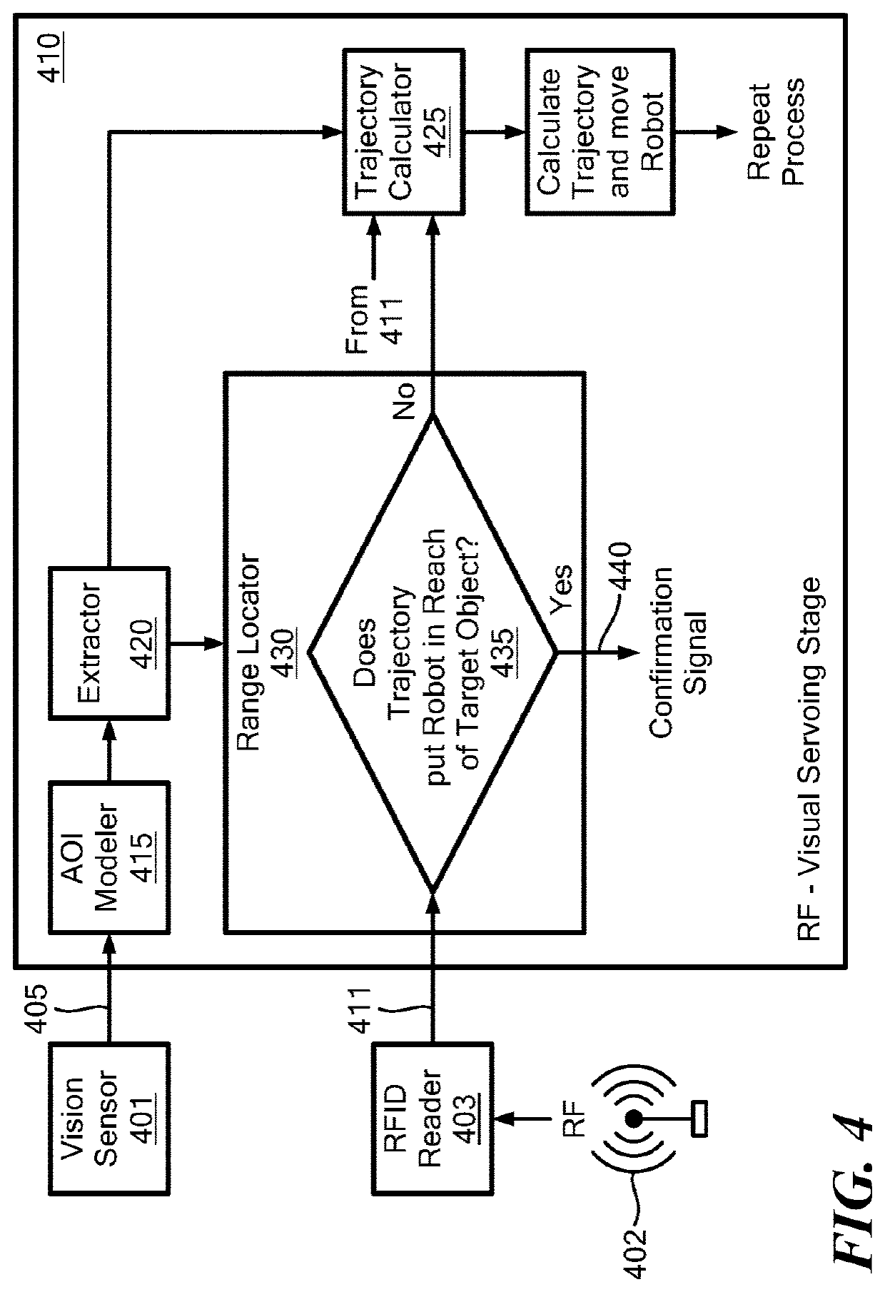
A control system and method locates a partially or fully occluded target object in an area of interest. The location of the occluded object may be determined using visual information from a vision sensor and RF-based location information. Determining the location of the target object in this manner may effectively allow the control system to “see through” obstructions that are occluding the object. Model-based and/or deep-learning techniques may then be employed to move a robot into range relative to the target object to perform a predetermined (e.g., grasping) operation. This operation may be performed while the object is still in the occluded state or after a decluttering operation has been performed to remove one or more obstructions that are occluding light-of-sight vision to the object.

Description

CROSS-REFERENCE TO RELATED APPLICATIONS[0001]This application claims benefit to U.S. Provisional Patent Application No. 63 / 119,544, filed on Nov. 30, 2020, the contents of which is incorporated by reference herein in its entirety.FIELD[0002]One or more embodiments described herein relate to systems and methods for performing location determination and / or robot control.BACKGROUND[0003]Robotic and other types of mechanical systems are used in many commercial, industrial and scientific applications. Examples include product manufacturing, surgical procedures, warehouse management, sample gathering and space exploration, just to name a few.[0004]To carry out their intended tasks, many of these systems are equipped with one or more image sensors, i.e., cameras. The sensors may be helpful in locating target objects, especially in what are considered to be unstructured environments. For example, a warehouse robot having an image sensor may be given the task to retrieve a desired object fro...

Claims


Application Information

Patent Timeline
Patent Type & Authority Applications(United States)
IPC IPC(8): B25J9/16G06K7/10G06K19/07G05B19/4155
CPCB25J9/1697G06K7/10366G05B2219/40269G05B19/4155G06K19/0723B25J9/1664G05B2219/40494
Inventor BOROUSHAKI, TARAADIB, FADELLENG, JUNSHAN
Owner MASSACHUSETTS INST OF TECH
Why Eureka
Try Eureka