Control system for and method of controlling product delivery systems

a control system and product technology, applied in the direction of electrical programme control, program control, instruments, etc., can solve the problems of difficult to achieve the effect of reducing the cycle time of vending, not providing a simple means for calibrating, programming and/or re-programming the control system, and not providing a simple means for reducing and/or monitoring vend failures

Active Publication Date: 2014-09-02
FASTCORP 3
View PDF11 Cites 0 Cited by
  • Summary
  • Abstract
  • Description
  • Claims
  • Application Information

AI Technical Summary

Benefits of technology

[0011]In a preferred embodiment, the positioning system includes a cable and reel device to lower and raise the vacuum picker head with respect to the position of the robotic manipulator. The cable is spooled onto the reel to raise the vacuum picker head, and the cable may be unwound to lower the vacuum picker head. In one embodiment, the cable includes one or more conductors that transmit electrical power to the vacuum picker head and transmit control signals between the vacuum picker head and the controller. In another embodiment the cable is comprised of a generally inelastic material along its axial length. The use of an inelastic material increases accuracy of positioning of the picker head, in that as the cable is wound or unwound on the reel, the total length of the cable generally remains unchanged.
[0012]In preferred embodiments, the controller of the present invention controls the rotation of the robotic manipulator arm segments, the lowering and raising of the vacuum picker head, and the activation and deactivation of the vacuum pump contained within the vacuum picker head. The controller monitors the current draw of the vacuum pump to determine if a product is held by the vacuum pump while the vacuum pump is running. A detected increase in the current draw of the vacuum pump is utilized by the control system to determine that a vacuum is being generated, and therefore, that a product is held by the vacuum picker. The controller is capable of monitoring the current draw of the vacuum pump in conjunction with the rotational motion of each arm segment so as to determine the precise location and orientation of the vacuum pump when a product drop (or vend failure occurs). This enables the controller to attempt to adjust for, correct or otherwise overcome the cause of the vend failure. In preferred embodiments, the controller is also capable of increasing or decreasing the power delivered to the drive system of each arm segment in a coordinated manner and in conjunction with monitoring of the rotational motion of each arm segment to reduce vend cycle time and maximize vend success. In preferred embodiments, the controller utilizes the monitoring of current draw of the vacuum pump and / or the monitoring of the rotational motion of each arm segment of the robotic manipulator to aid in calibrating, programming and / or re-programming the control system.
[0018]In the controller of a preferred embodiment there is a menu driven programming / set-up function. This programming function requires that upon installation or setup of a machine a technician (such as the operator or machine installer of the operator) define the bin location, price of product, selection number and bin height among other parameters. The programming function further requires that the technician define a “product depth” or “number of products” that are, or will / may be contained inside the bin when it is full (whether it is a tall bin or a short bin). By defining product “depth” or by defining the number of products that fit in a full bin, the controller uses the product sensor to read the difference in height from the home position in the machine to the depth (top surface) of the product in that bin and then calculate (utilizing bin height) how many products are in each bin, in total, when the door gets closed. This combination of a sensor and a control algorithm give the operator the assurance of product quantity each and every fill. It gives a closed loop system by providing exact product count at each visit upon door closure and leaves no opportunity to “cheat” the inventory system.

Problems solved by technology

Frozen food vending can present certain challenges to dispensing because some of the components required to activate the dispensing mechanism are often enclosed within the freezer compartment, creating a harsh environment in which those components must operate.
Notwithstanding the improvements these features provide over the prior art, among other disadvantages, the control system of U.S. Pub. No. 2008 / 0093371 does not provide a simple means for calibrating, programming and / or re-programming the control system, and does not provide a means for reducing and / or monitoring vend failures.
This process has an inherent error factor.

Method used


Image

  • Control system for and method of controlling product delivery systems
  • Control system for and method of controlling product delivery systems

Examples


Embodiment Construction

[0022]As required, a detailed embodiment of the present invention is disclosed herein; however, it is to be understood that the disclosed embodiment is merely exemplary of the principles of the invention, which may be embodied in various forms. Therefore, specific structural and functional details disclosed herein are not to be interpreted as limiting, but merely as a basis for the claims and as a representative basis for teaching one skilled in the art to variously employ the present invention in virtually any appropriately detailed structure.

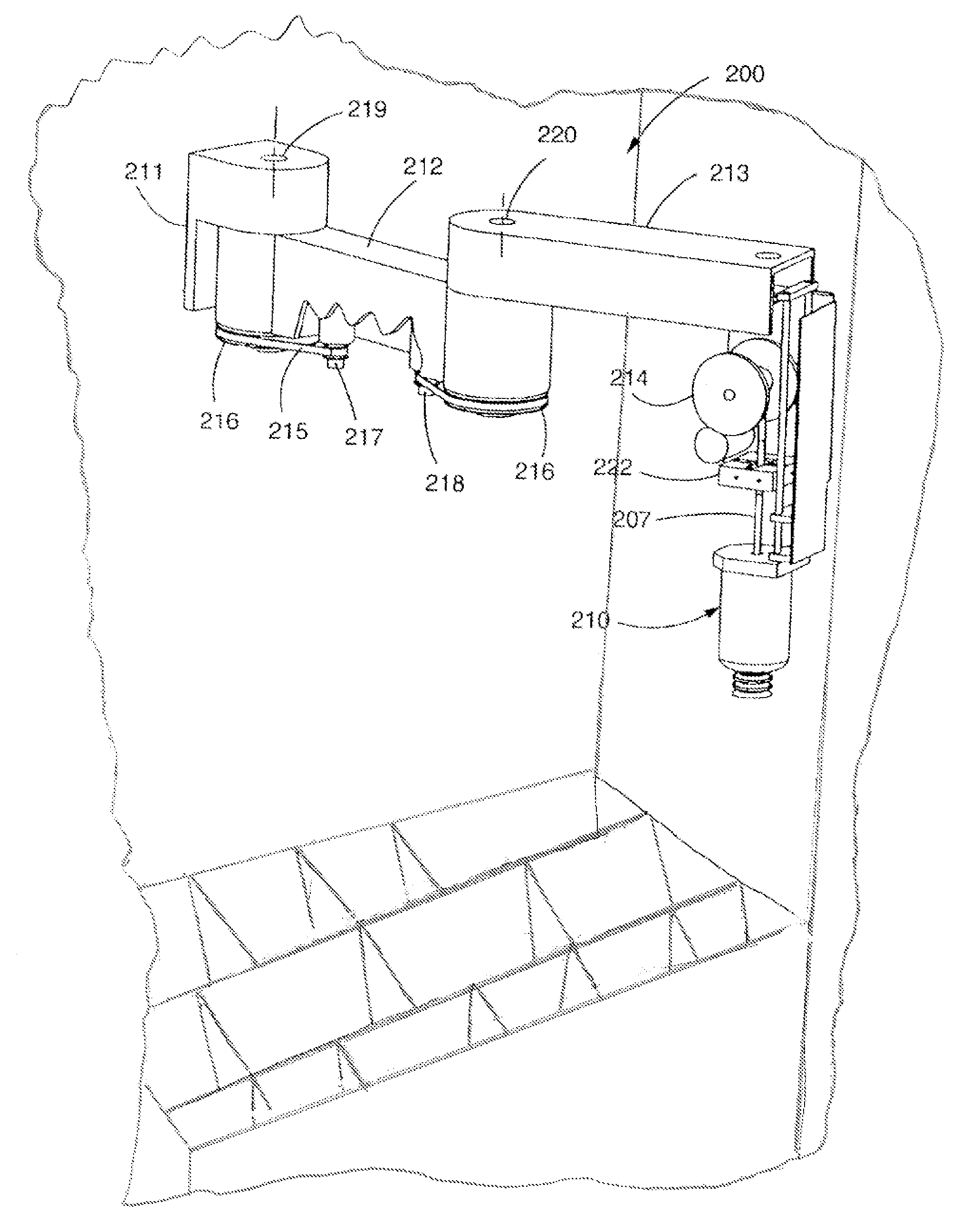
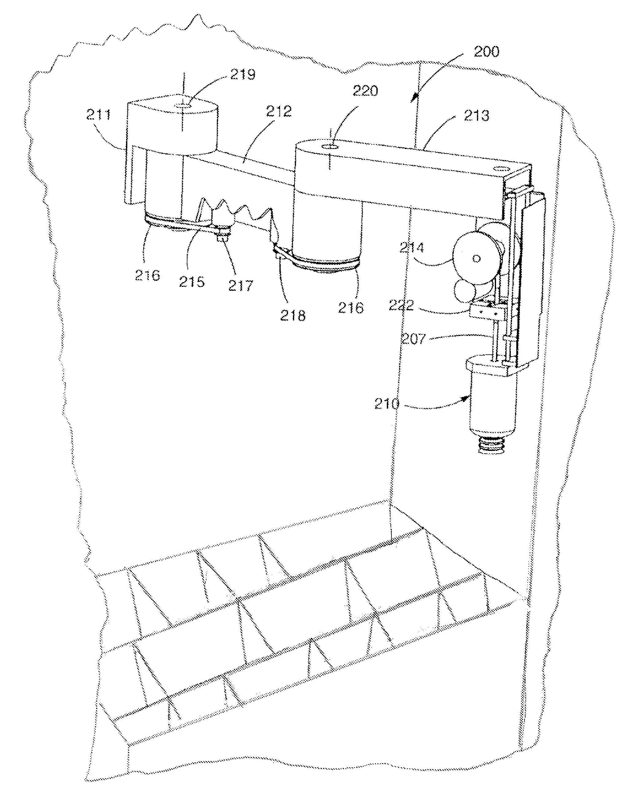
[0023]Referring to FIG. 1, a partial perspective view of a vending machine is shown. The vending machine includes a generally rectangular housing (or cabinet) having a top wall, bottom wall, side walls, and a rear wall that define an open interior cavity. A door functions as a removable (or partially removable) front wall for the interior cavity of the vending machine. Delivery system 200, which includes vacuum picker head assembly 210 coupled...


PUM


Abstract

A control system for and methods of controlling a product delivery system are provided.

Description

CROSS-REFERENCE TO RELATED APPLICATIONS[0001]This application claims priority pursuant to 35 U.S.C. 119(e) to co-pending U.S. Provisional Patent Application Ser. No. 61 / 264,318, filed Nov. 25, 2009, the entire disclosure of which is incorporated herein by reference.FIELD OF THE INVENTION[0002]The present invention relates generally to product delivery systems. More specifically, the present invention is concerned with product delivery systems such as vending machines and the like, and control systems and methods of controlling the same.BACKGROUND OF THE INVENTION[0003]The dispensing process for vending varies according to the application. For example, a common dispensing process for bottled and canned beverage vending machines has motors for rotating an oscillator that, depending on the position and angle of rotation, will dispense the container (can or bottle) when activated. In other bottle and can vending machines, a carriage is maneuvered horizontally and vertically to position ...

Claims


Application Information

Patent Timeline
Patent Type & Authority Patents(United States)
IPC IPC(8): G06F7/00G06F19/00G05B19/04
CPCG07F11/24B25J9/042B25J9/044B25J9/1692G05B2219/39048G07F9/026G07F11/10G07F11/165B25J9/16B25J15/0616B65G1/04G07F11/1657
Inventor BOYER, JEFFPIATNIK, JOSEPH TODDUBIDIA, FERNANDO A.STEIN, AARON M.LEWIS, JOHN F.
Owner FASTCORP 3
Why Eureka
Try Eureka