
Flash lidar

Pending Publication Date: 2022-06-02
SUTENG INNOVATION TECH CO LTD
View PDF0 Cites 0 Cited by
  • Summary
  • Abstract
  • Description
  • Claims
  • Application Information

AI Technical Summary

Benefits of technology

The flash LiDAR described in this patent uses a special design to detect objects in a space using laser scanning. It includes an emitting assembly and a receiving assembly that work together to create a detection region. Unlike other flash LiDARs, this design ensures that stray light is blocked from interfering with the detection of the reflected laser. This allows for accurate and efficient detection of short-range objects and helps improve safety. The control assembly identifies the target object using the reflected laser, reducing blind spots and improving efficiency of the flash LiDAR.

Problems solved by technology

However, a receiving assembly of the existing LiDAR cannot receive sufficient light signals reflected by the target object in the near field, thereby causing inaccurate detection results in the near field.

Method used


Image

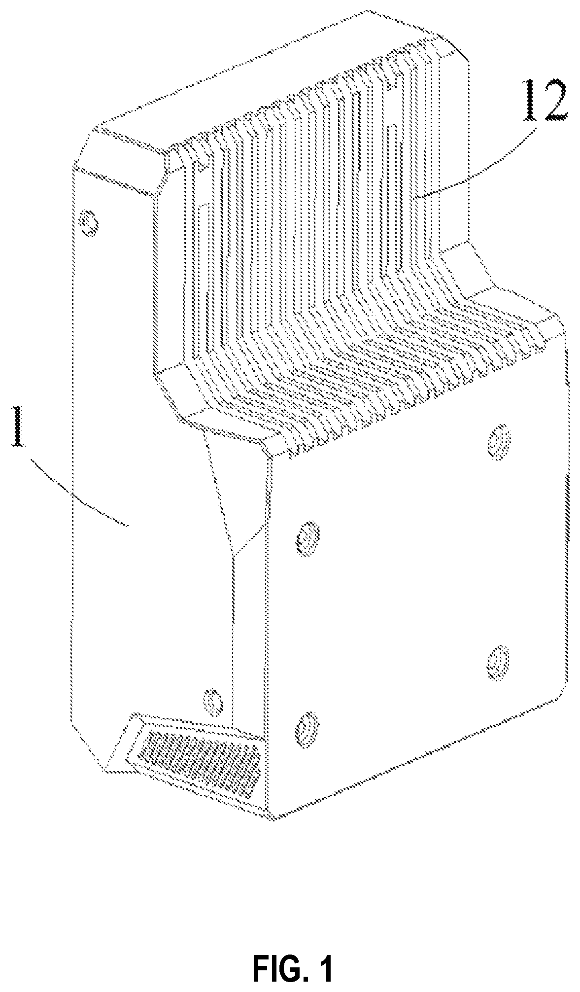
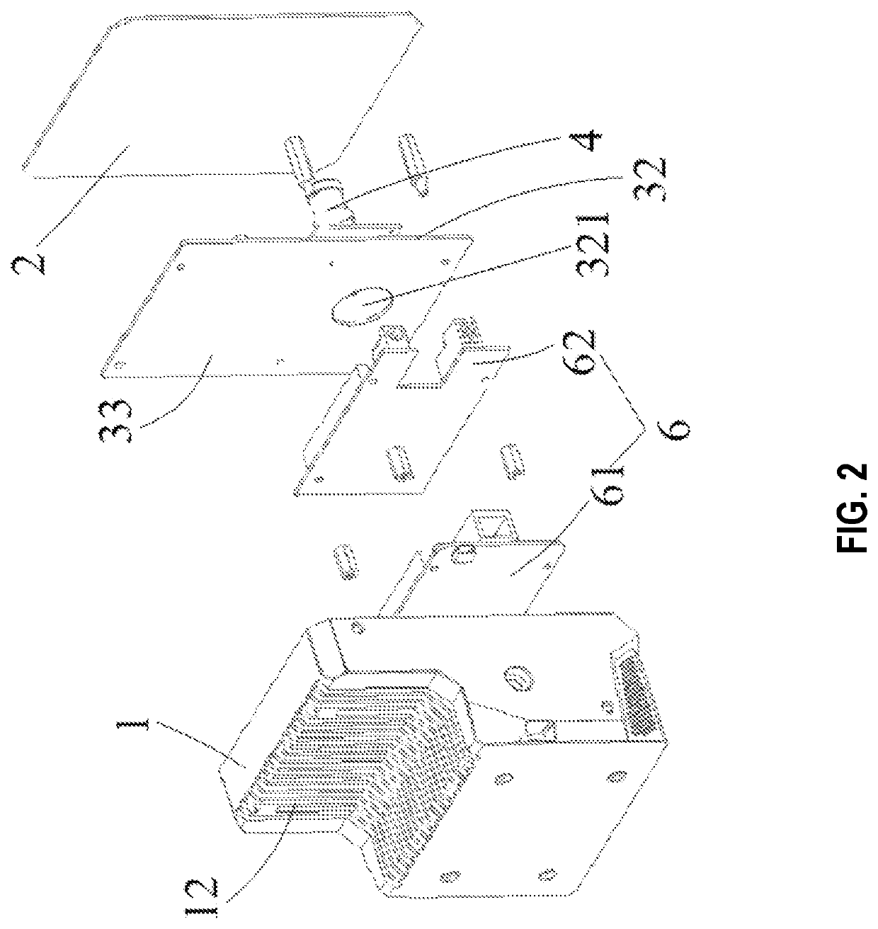
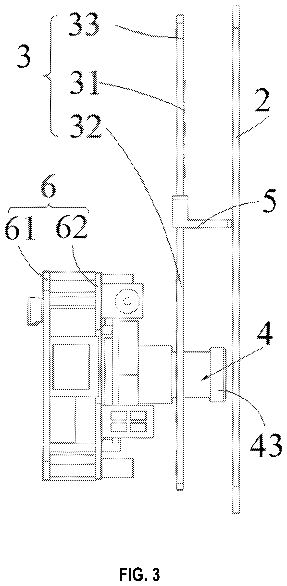
  • Flash lidar
  • Flash lidar
  • Flash lidar

Examples


Embodiment Construction

[0046]To more clearly describe the technical problems to be solved with this disclosure, technical solutions, and beneficial effects, the following further describes this disclosure in detail with reference to the accompanying drawings and embodiments. It should be understood that the specific embodiments described herein are only used to explain this disclosure, and are not intended to limit this disclosure.

[0047]It should be noted that when being “fastened to” or “provided on” another element, an element can be directly or indirectly located on the another element. When being “connected to” another element, an element can be directly or indirectly connected to the another element.

[0048]It should be understood that azimuth or position relationships indicated by terms such as “length,”“width,”“above,”“under,”“front,”“rear,”“left,”“right,”“vertical,”“horizontal,”“top,”“bottom,”“inner,” and “outer” are based on the azimuth or position relationships shown in the accompanying drawings, ...


PUM


Abstract

A flash LiDAR is provided and includes: an emitting assembly (3), a receiving assembly (4), a light blocking element (5), and a control assembly (6). The emitting assembly (3) includes at least one light-emitting element (31), configured to emit an outgoing laser to a detection region; the receiving assembly (4) is configured to receive a reflected laser returning after being reflected by an object in the detection region, where the emitting assembly (3) and the receiving assembly (4) are arranged abreast; and the light blocking element (5) is configured to block stray light directed to the receiving assembly (4).

Description

CROSS-REFERENCE TO RELATED APPLICATION[0001]The present application is a continuation of International Application No. PCT / CN2019 / 100568, filed on Aug. 14, 2019, and also claims priority to Chinese Patent Application No. 201980002317.X, filed on Nov. 11, 2019, both of which are incorporated herein by reference in their entireties.TECHNICAL FIELD[0002]The present application relates to the field of radar, and in particular, relates to flash LiDAR.BACKGROUND[0003]A LiDAR is a system for emitting an outgoing laser to detect position, velocity, and other feature values of a target object, and is widely applied to the field of laser detection. The LiDAR is alternatively a system for emitting a laser of a specific wavelength in a specific direction to detect position, velocity, and other feature values of a target object.[0004]During operation of the LiDAR, an outing laser emitted by a light source reaches the target object, and then is reflected by the target object. The reflected laser ...

Claims


Application Information

Patent Timeline
Patent Type & Authority Applications(United States)
IPC IPC(8): G01S7/481
CPCG01S7/4814G01S7/4813G01S7/4815G01S17/894
Inventor HOU, SONGSHAN
Owner SUTENG INNOVATION TECH CO LTD
Learn More