
Battery sub-packing unit

Pending Publication Date: 2022-06-02
SK ON CO LTD
View PDF0 Cites 0 Cited by
  • Summary
  • Abstract
  • Description
  • Claims
  • Application Information

AI Technical Summary

Benefits of technology

The patent is about a device that prevents batteries from catching fire and exploding. This can be useful for people who work with batteries in a dangerous environment.

Problems solved by technology

However, such an electrode assembly generates heat while undergoing charging and discharging of electrical energy, and an increase in temperature due to such generation of heat may deteriorate performance of the secondary battery cell.
In addition, when such generation of heat becomes severe, an internal pressure of the secondary battery cell may rise, resulting in a problem in which the secondary battery cell ignites.
Moreover, when a plurality of secondary battery cells are mounted, such as in an electric vehicle, an energy storage system (ESS), or the like, the secondary battery cell may explode with such ignition, and flames thereof may be propagated to an adjacent secondary battery cell.
That is, there may be a problem in that gas, flames, or the like, generated in the secondary battery cell, may not be discharged to an external space, but may explode in a chain reaction while propagating to an adjacent secondary battery cell.

Method used


Image

  • Battery sub-packing unit
  • Battery sub-packing unit
  • Battery sub-packing unit

Examples


first embodiment

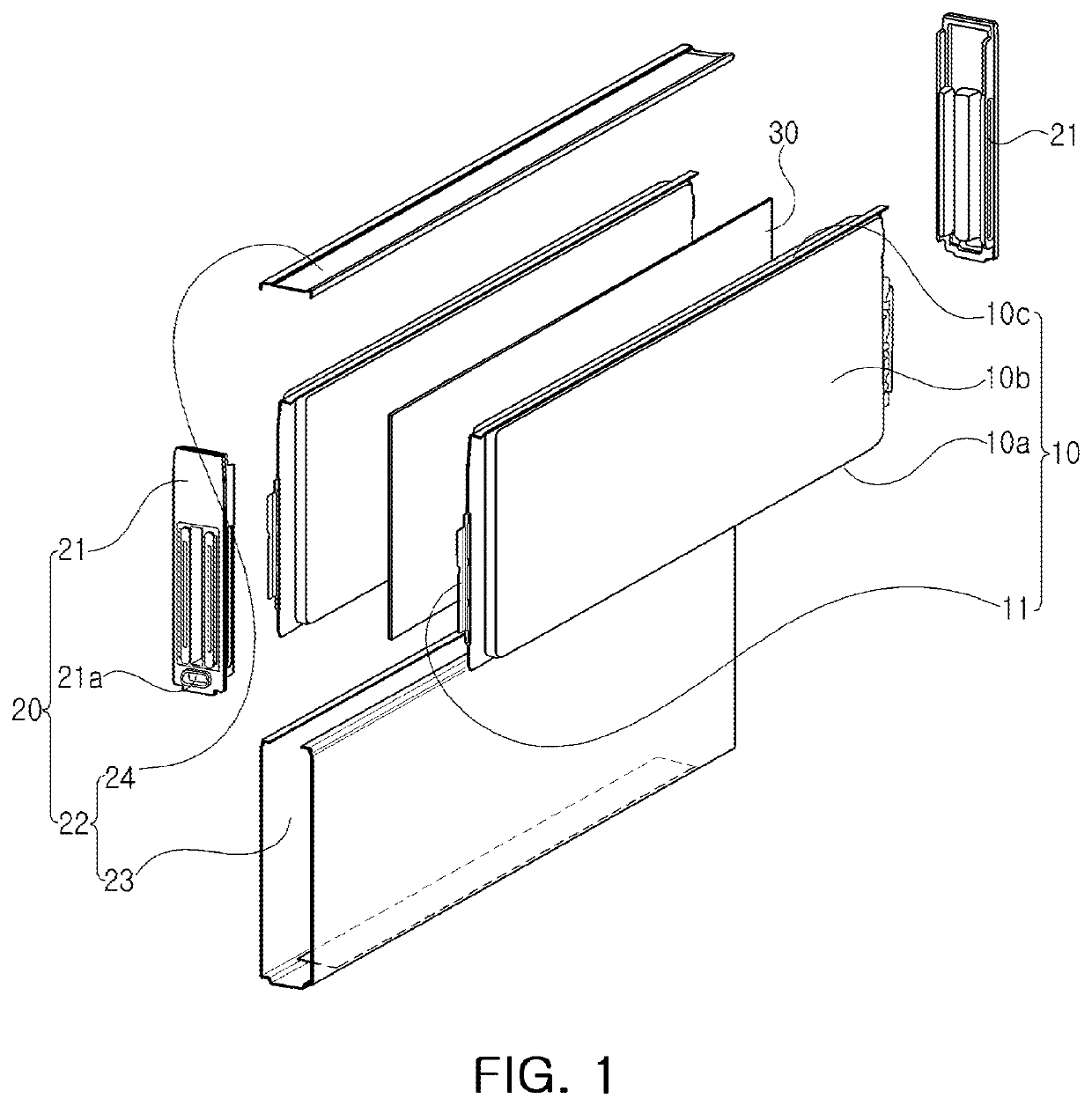
[0073]In this case, when the surrounding cover 22 is formed of an aluminum material, it may be provided as the surrounding cover 22. This maybe because the aluminum material has excellent formability, and allows performing an extrusion molding process and a die casting process.

[0074]In addition, when the surrounding cover 22 is formed of a stainless steel material, it may be provided as the second embodiment of the surrounding cover 22. This maybe because the stainless steel material has lower formability than the aluminum material, and may be difficult to maintain a shape thereof due to spring back after performing a press forming process and a bending forming process. For example, the second embodiment of the surrounding cover 22 may make firm coupling while improving a problem caused by the spring back occurring after forming the surrounding cover 22.

[0075]In addition, if the material of the surrounding cover 22 is formed of a metal material having a melting point of 1000° C. or ...

second embodiment

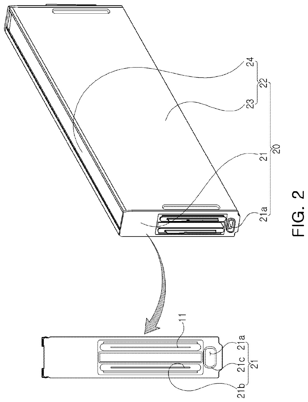
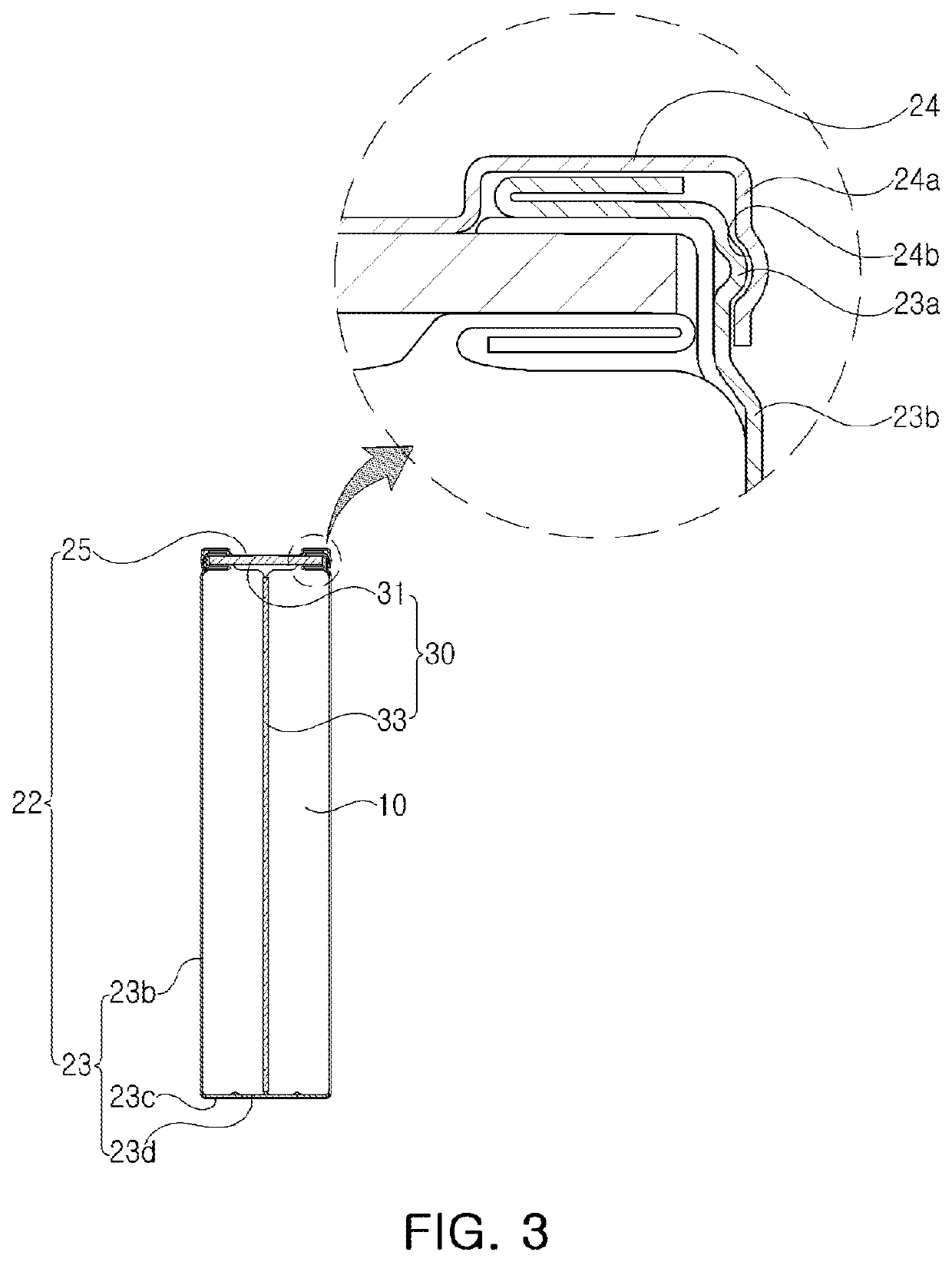
[0088]Referring to the drawings, a surrounding cover 22 of a battery sub-packing unit according to an embodiment may include an accommodating can 23 and an upper fastening portion 25. As described above, the surrounding cover 22 including the accommodating can 23 and the upper fastening portion 25 may be a configuration of the surrounding cover 22.

[0089]In this case, the accommodating can 23 may have both end portions to which an end panel 21 is respectively coupled, and may surround a lower surface portion 10a and a side surface portion 10b of a battery cell 10. The upper fastening portion 25 may extend from side wall portions 23b of the accommodating can 23 opposing each other, may be arranged to have a shape bent in a direction of an upper surface portion 10c of the battery cell 10, and may be fastened to each other as a pair of upper fastening portions to surround the upper surface portion 10c of the battery cell 10.

[0090]As such, at least one battery cell 10 may be accommodated...


PUM


Abstract

A battery sub-packing unit includes at least one battery cell; and a case accommodating the at least one battery cell, wherein the case comprises an end panel on which an electrode tab of the at least one battery cell is fastened to extend into an external space, and having a lower end portion in which a sub-vent hole is formed for communication between the external space and an internal space in which the at least one battery cell is disposed.

Description

CROSS-REFERENCE TO RELATED APPLICATION(S)[0001]This application claims benefit of priority to Korean Patent Application No. 10-2020-0164098 filed on Nov. 30, 2020 in the Korean Intellectual Property Office, the disclosure of which is incorporated herein by reference in its entirety.BACKGROUND1. Field[0002]The present disclosure relates to a battery sub-packing unit.2. Description of Related Art[0003]As technological developments and demand for mobile devices, electric vehicles, and energy storage systems (ESS) increase, the demand for secondary battery cells as an energy source is rapidly increasing. A secondary battery cell is a battery capable of repeating charging and discharging of electrical energy, because mutual conversion between chemical energy and electrical energy are reversible.[0004]Such a secondary battery cell may include an electrode assembly such as a positive electrode, a negative electrode, a separator, and an electrolyte, main components of the secondary battery,...

Claims


Application Information

Patent Timeline
IPC IPC(8): H01M50/24H01M10/0525H01M50/209
CPCH01M50/24H01M50/209H01M10/0525H01M50/202H01M50/258H01M50/264H01M50/227H01M50/211H01M50/224H01M50/293H01M50/273H01M50/262H01M50/30H01M50/249A62C5/006A62C99/0027H01M2220/20Y02E60/10
Inventor JEON, HAE RYONGCHOI, YANG KYUKIM, TAE IILEE, KANG GU
Owner SK ON CO LTD
Learn More