Intercooled Cascade Cycle Waste Heat Recovery System

a waste heat recovery and cascade cycle technology, applied in the direction of steam engine plants, gas turbine plants, machines/engines, etc., can solve the problems of waste heat recovery systems with additional limitations, waste heat recovery systems with higher cost per unit of power produced, and long response time to initial thermal input, etc., to improve the design of high-density working fluid systems, improve efficiency, and reduce size

Active Publication Date: 2022-06-09
INDUSTROM POWER LLC
View PDF19 Cites 3 Cited by
  • Summary
  • Abstract
  • Description
  • Claims
  • Application Information

AI Technical Summary

Benefits of technology

[0006]According to one aspect of the present disclosure, there are provided methods and apparatus to improve high-density working fluid system design, thereby optimizing efficiency, reducing size, lowering cost, and improving start times, among other benefits. The design presented herein is well suited to operate with supercritical working fluids having critical temperatures below 200 degrees Celsius.

Problems solved by technology

Methods exist for utilizing this waste heat in a separate system or cycle to generate additional mechanical work or electrical energy (known as waste heat recovery systems), however these waste heat recovery systems typically have a higher cost per unit of power produced (referred to in the industry as specific cost) and a larger system volume per unit power produced (referred to as specific volume) than systems utilizing non-waste heat sources.
They also suffer from a lengthy time of response to initial thermal input into the system.
Waste heat recovery systems have additional limitations.
A Rankine power cycle is used and the usual waste heat temperature range falls between 300 and 900 degrees C. Conventional waste heat recovery systems are also commonly large-scale, stationary, and costly.
Organic hydrocarbons, as an alternative, are not environmentally friendly.
Moreover, conventional waste heat recovery systems require a significant amount of time to start—usually 60 minutes, or more.

Method used


Image

  • Intercooled Cascade Cycle Waste Heat Recovery System
  • Intercooled Cascade Cycle Waste Heat Recovery System
  • Intercooled Cascade Cycle Waste Heat Recovery System

Examples


Embodiment Construction

[0022]As used herein, “a” and “an” means one or more than one unless otherwise stated. As it is used in the claims or specification, the term “or” is intended to encompass both exclusive and inclusive cases. In other words, “A or B” is intended to be synonymous with “at least one of A and B,” unless otherwise expressly specified herein.

[0023]The power generation cycle disclosed herein uses a working fluid in piping. Directions of fluid flow through said piping during steady state operations of the power cycle are indicated by arrow in the figures herein provided. One of ordinary skill in the art of power systems would understand the direction even without said arrows as moving from regions of higher pressure to regions of lower pressure. A person of skill in the art would also understand the meaning of upstream and downstream.

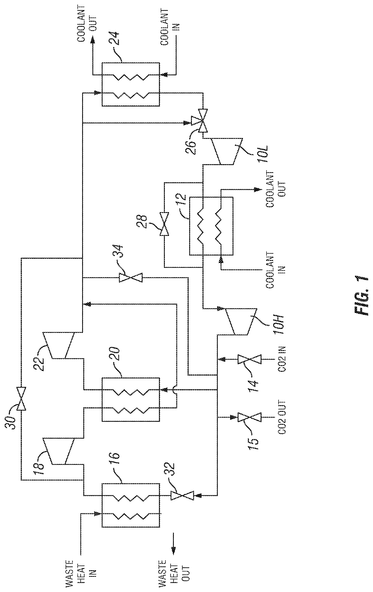
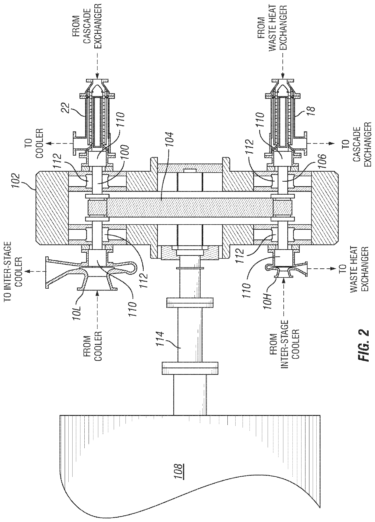
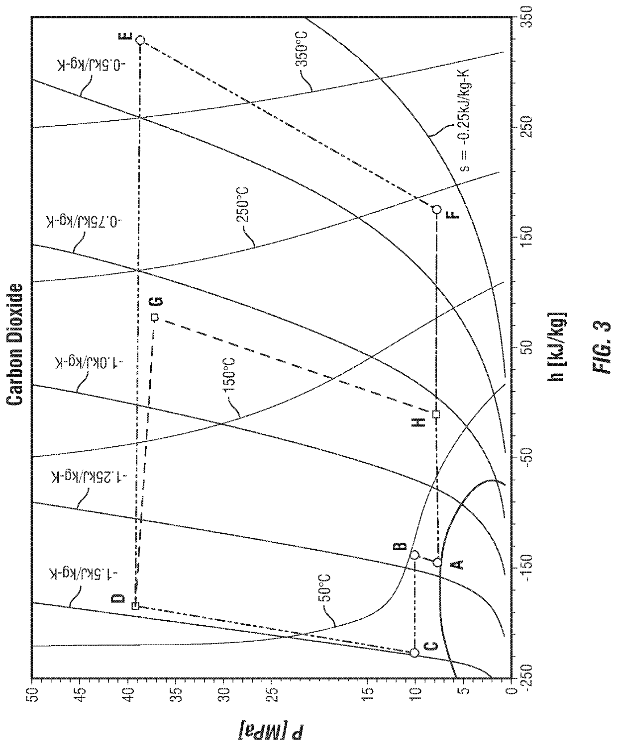
[0024]Presented herein is a power generation system using high-density working fluid, such as supercritical carbon dioxide. This system is adapted to overcome ...


PUM


Abstract

Provided herein is a power generation system and method for transforming thermal energy, such as waste heat, into mechanical energy and / or electrical energy. The system employs features designed to accelerate start times, reduce size, lower cost, and be more environmentally friendly. Tire system may include multiple compressors on separate pinion shafts with multiple expanders, a temperature valve upstream of compressors with a mass management system downstream, an intercooler between compressors, and a cascade exchanger. In one embodiment, the system is configured to drive a synchronous generator, with the separate pinion shafts rotating at two separate, but constant, speeds.

Description

CROSS-REFERENCE TO RELATED APPLICATIONS[0001]The present application claims priority to U.S. provisional application Ser. No. 61 / 814,827, which was filed on Mar. 6, 2019, entitled Intercooled Cascade Cycle Supercritical CO2 Waste Heat Recovery System, the disclosure of which is incorporated by reference herein in its entirety.TECHNICAL FIELD[0002]This invention generally relates to systems and methods for waste heat recovery and power generation systems using high pressure working fluids such as supercritical carbon dioxide.BACKGROUND OF THE INVENTION[0003]Many methods and systems exist for generating electricity by the transfer and conversion of heat into mechanical or electrical energy. Systems where the hot source fluid is not recycled, but rather, is discarded or removed by external means are known as waste heat sources. Methods exist for utilizing this waste heat in a separate system or cycle to generate additional mechanical work or electrical energy (known as waste heat recov...

Claims


Application Information

Patent Timeline
Patent Type & Authority Applications(United States)
IPC IPC(8): F01D13/00F01K25/10F01K7/02F01K7/32
CPCF01D13/00F01K7/32F01K7/02F01K25/103F02C3/107F02C1/04F02C1/08F02C3/22F02C7/36F05D2220/76F05D2220/60F05D2220/75F01D15/08F01D15/10F01D15/12
Inventor ANGEL, PAULHARRIS, JOSEPH
Owner INDUSTROM POWER LLC
Why Eureka
Try Eureka