Self-ligating orthodontic bracket

a self-ligating, orthodontic technology, applied in brackets, arch wires, etc., can solve the problems of affecting the latch mechanism, and affecting the stability of the brack

Pending Publication Date: 2022-06-30
HIRSCH DYNAMICS HLDG AG
View PDF3 Cites 0 Cited by
  • Summary
  • Abstract
  • Description
  • Claims
  • Application Information

AI Technical Summary

Problems solved by technology

A disadvantage of the prior art pursuant to a first aspect is that the beam has to be inserted into the bracket body in the mesial-distal direction, whereby in practice it can be tedious to maneuver the beam into the opening, especially if there is little space around the orthodontic bracket as e.g. for treatments of molar teeth.
Moreover, an assembly and disassembly is uncomfortable due to the hidden placement of the beam inside the bracket body and hence, trained technical staff and specific tools are required to reach the beam.
Due to the opening of the bracket body, impurities can enter the orthodontic bracket and harm the latch mechanism, whereby in addition food leftovers can interlock with the opening of the bracket body.
A disadvantage of the prior art pursuant to a second aspect is that the at least one covering door requires elaborate geometries for surpassing the beam, whereby especially with respect to laborious processing of material of the covering door manufacturing costs are high.
Besides that, if forces act on the covering door in the closed position in a gingival direction, the covering door can undesirably move (in particular by the play between the covering door and the bracket body) from a closed position into an open position, in which an arch wire can move out of the arch wire slot.
A disadvantage of the prior art pursuant to a third aspect is that a high play between the covering door and the bracket body is required to be able to surpass the beam to reach the closed position, whereby a tight fit is not possible and impurities tend to reach an interior area of the orthodontic bracket as well.

Method used


Image

  • Self-ligating orthodontic bracket
  • Self-ligating orthodontic bracket
  • Self-ligating orthodontic bracket

Examples


Embodiment Construction

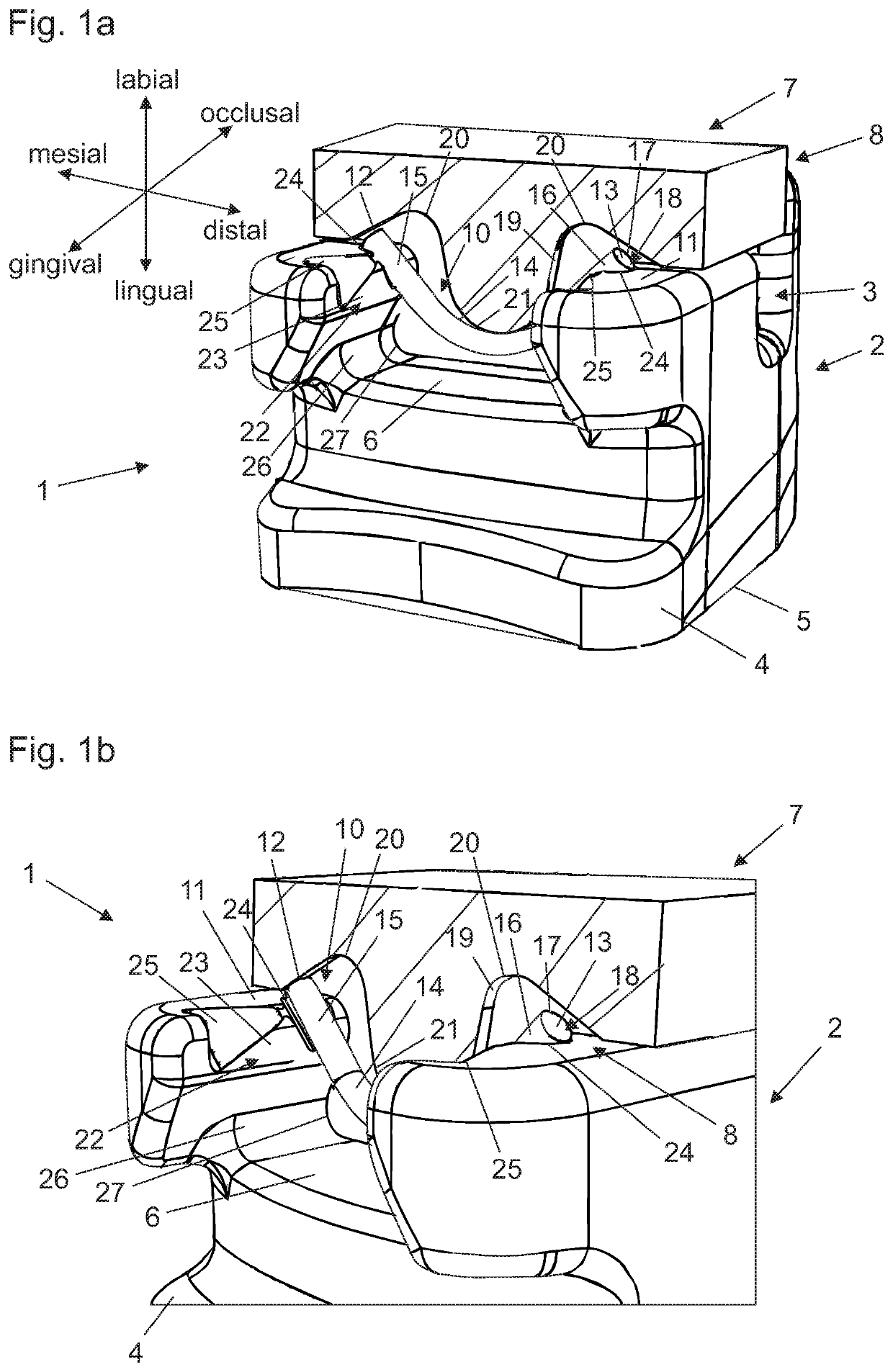
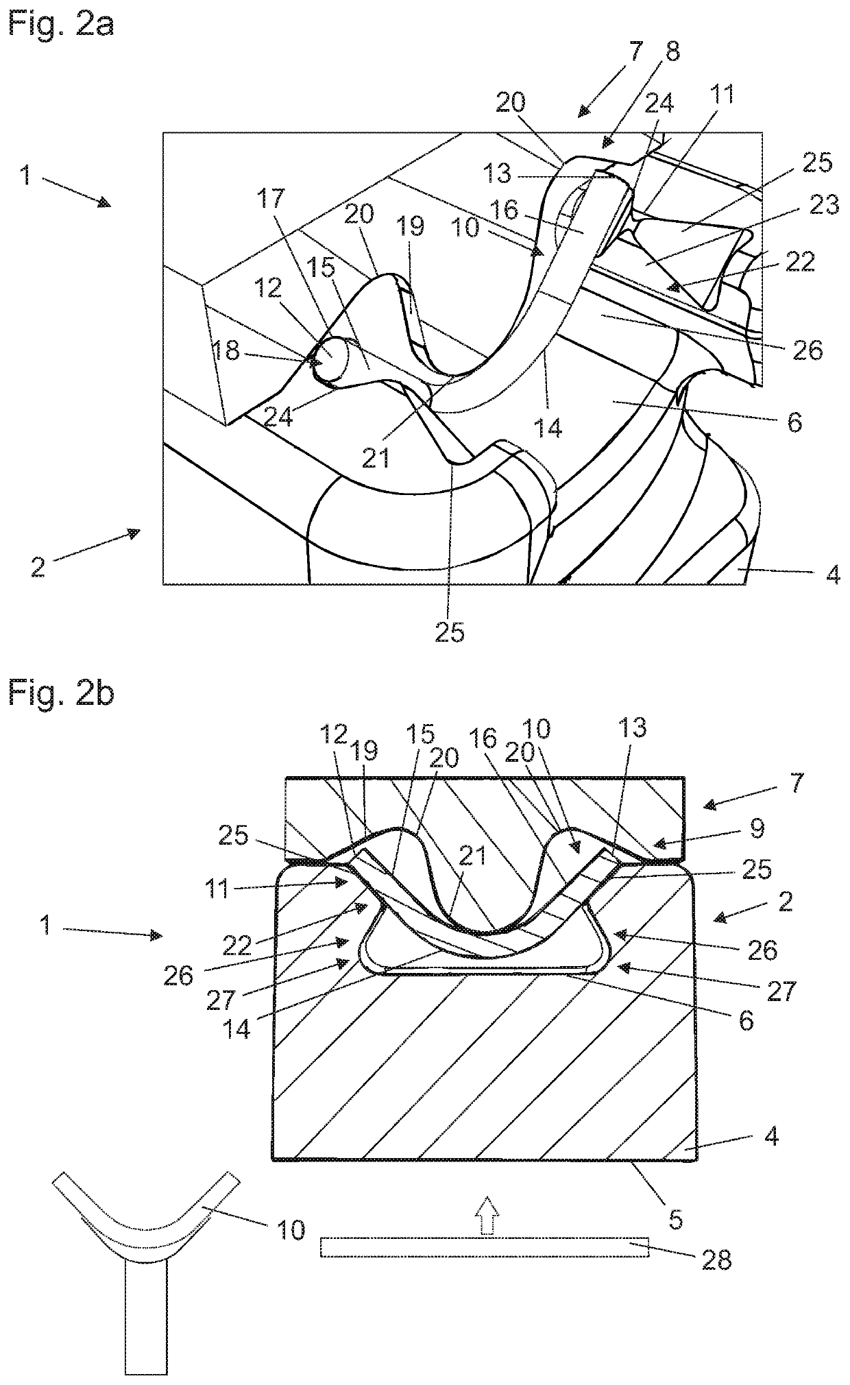
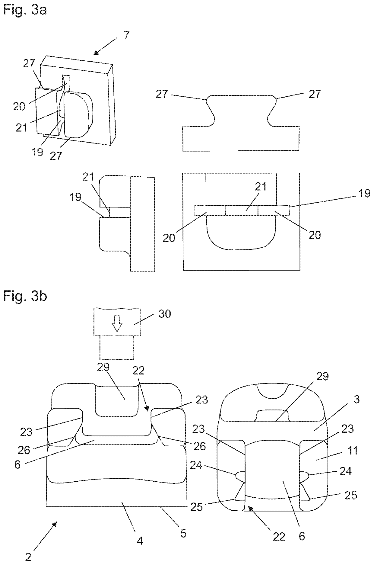
[0084]FIG. 1 shows a self-ligating orthodontic bracket 1, the orthodontic bracket 1 comprising a bracket body 2 having a mesial-distal arch wire slot 3 extending in a labial direction of the bracket body 2. The orthodontic bracket 1 comprises a base 4 with a bonding surface 5 and a channel 6 oriented perpendicularly to the arch wire slot 3.

[0085]A covering door 7 is connected to the bracket body 2 which is suitable to occlude the arch wire slot 3 in a closed position 8 and to allow access to the arch wire slot 3 in an open position 9 (cf. FIG. 2b). The covering door 7 is cut in half behind the securing device 10 in a mesial-distal and labial-lingual plane in occlusal direction to disclose the securing device 10 that is hidden in the orthodontic bracket 1 once assembled so that the securing device 10 is exhaustively enclosed within the orthodontic bracket 1. The covering door 7 is slidably coupled to the bracket body 2, whereby the covering door 7 is linearly moveable between the clo...


PUM


Abstract

A self-ligating orthodontic bracket has a bracket body having a mesial-distal arch wire slot extending in a labial direction of the bracket body, a base with a bonding surface and a channel oriented essentially perpendicular to the arch wire slot. There is at least one covering door for occluding the arch wire slot in a closed position and opening the arch wire slot in an open position. The at least one covering door is slidably coupled to the bracket body and is essentially linearly moveable between the closed position and the open position. There is at least one securing device orientated essentially parallel to the arch wire slot. The at least one securing device is completely arranged within the orthodontic bracket, completely enclosed by the bracket body and the at least one covering door in the closed position, the open position and in all intermediate positions.

Description

BACKGROUND OF THE INVENTION[0001]The present invention relates to a self-ligating orthodontic bracket comprising a bracket body having an arch wire slot as well as a base, at least one covering door suitable for occluding the arch wire slot and at least one securing device. The present invention further relates to a method for assembling a self-ligating orthodontic bracket.[0002]A self-ligating orthodontic bracket is shown in WO 2019 / 150257 A1, whereby a latch mechanism is used in the form of a beam extending in a mesial-distal direction across a portion of an opening of a bracket body perpendicular to a sliding direction of a covering door to fix a closed position in which an arch wire slot is occluded. The covering door is secured by the beam in an occlusal-gingival direction, whereby the covering door occludes the beam in a labial direction by surpassing the beam with the help of a deflecting protrusion of the covering door.[0003]A disadvantage of the prior art pursuant to a firs...

Claims


Application Information

Patent Timeline
Patent Type & Authority Applications(United States)
IPC IPC(8): A61C7/28
CPCA61C7/287
Inventor HIRSCH, MARKUS
Owner HIRSCH DYNAMICS HLDG AG
Why Eureka
Try Eureka