Transflective liquid crystal display

a liquid crystal display and transparent technology, applied in non-linear optics, instruments, optics, etc., can solve the problems of difficult manufacturing and more expensive double cell gap designs, and achieve the effects of easy manufacturing, easy and economical manufacturing, and easy manufacturing

Active Publication Date: 2012-02-21
THE HONG KONG UNIV OF SCI & TECH
View PDF12 Cites 4 Cited by
  • Summary
  • Abstract
  • Description
  • Claims
  • Application Information

AI Technical Summary

Benefits of technology

[0005]In the present disclosure, a new transflective LCD is disclosed, having excellent optical properties, including good optical efficiency in both the transmittive and reflective modes, and excellent contrast and viewing angles. The new transflective LCD also has the benefit of being generally easy to fabricate.
[0007]For the case of double-pixel designs, the two sub-pixels can be of equal cell gap, but are more commonly of different cell gaps. Different cell gaps can more easily be made to compensate for the difference in path lengths inside the LCD cell for the transmittive and reflective components. However, such double cell gap designs are more costly and difficult to manufacture. Moreover, in most known designs of this type, internal retardation films are needed to equalize the RVC and TVC of the sub-pixels.
[0008]In the present invention, the pixels of the LCD are divided into two sub-pixels, one for the reflective mode and one for the transmittive mode. However, the cell gaps of both sub-pixels are the same, making it easy to fabricate as compared to those designs requiring dual cell gaps. Additionally no internal retardation films are required, making the display easy and economical to fabricate.
[0009]More particularly, the present invention employs a novel photoalignment technique to achieve two different LCD modes for the reflective and for the transmittive sub-pixels. The photoalignment technique is used together with a shadow mask in an embodiment of the invention to achieve this effect. Double exposure of the alignment layer with different orientations can produce different alignment directions, thereby achieving the different LCD modes for the sub-pixels.

Problems solved by technology

However, such double cell gap designs are more costly and difficult to manufacture.

Method used


Image

  • Transflective liquid crystal display
  • Transflective liquid crystal display
  • Transflective liquid crystal display

Examples


Embodiment Construction

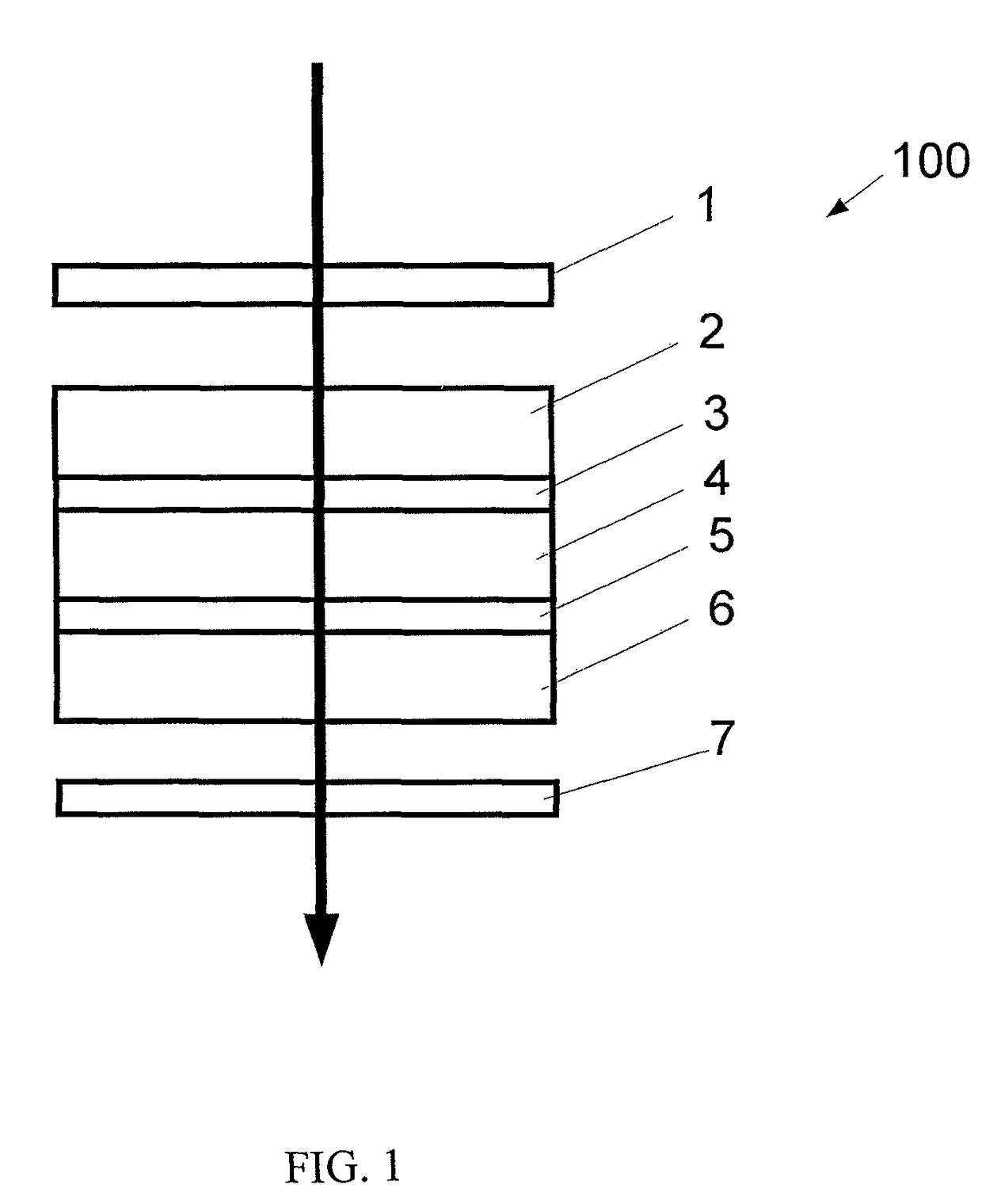
[0020]Referring now to the drawings, FIG. 1 shows a traditional liquid crystal (LC) cell structure 100. The LC cell consists primarily of (1) the glass substrates 2 and 6, with alignment layers 3 and 5 associated with them, and (2) the LC layer 4. In addition, front and rear polarizers 1 and 7 are needed to manifest the polarization manipulation of the LC cell and show bright or dark states of the display. Other structures such as the active matrix thin film transistors and spacers, retardation films etc are not shown here for the sake of clarity, but may also be used if desired or needed for a particular application or implementation.

[0021]The optical properties of the LC display 100 are defined by a twist angle and a retardation dΔn of the LC layer 4. Here d is the cell gap and Δn is the birefringence of the LC material. The alignment layers 3 and 5 determine the twist angle as well as the pretilt angle of the LC layer. Transparent conductive electrodes (not shown in FIG. 1) are e...


PUM

PropertyMeasurementUnit
angleaaaaaaaaaa
angleaaaaaaaaaa
angleaaaaaaaaaa

Abstract

Pixels of an LCD are divided into two sub-pixels, one for a reflective mode and one for a transmittive mode. The cell gaps of both sub-pixels are the same, improving fabrication ease. A novel photoalignment technique is used together with a shadow mask in an embodiment of the invention. Double exposure of the alignment layer with different orientations produces different alignment directions, thereby achieving the different LCD modes for the sub-pixels.

Description

FIELD OF THE INVENTION[0001]This invention relates generally to liquid crystal display technology and, more particularly, to a transflective liquid crystal display mode and methods of fabrication thereof.BACKGROUND[0002]Liquid crystal displays (LCDs) are used in many electronic products today. For example, with respect to mobile applications, a mobile device display should be viewable under strong ambient light as well as in the dark. In the dark, a backlight is provided so that the LCD operates in a transmittive mode, i.e., the generated light is transmitted through the LCD. When there is sufficient ambient light, the LCD should be able to operate in a reflective mode, meaning that the display is made visible by ambient light reflecting from the LCD. In order for both the reflective mode and the transmittive mode to be possible, the reflectance-voltage curve (RVC) and the transmittance-voltage curve (TVC) should overlap.[0003]Numerous types of transflective displays are known. For ...

Claims


Application Information

Patent Timeline
Patent Type & Authority Patents(United States)
IPC IPC(8): G02F1/1335G02F1/1343
CPCG02F1/133555G02F1/133788G02F1/1396G02F2001/133757G02F2202/40G02F1/133757
Inventor KWOK, HOI SINGCHIGRINOV, VLADIMIR GRIGORIEVICH
Owner THE HONG KONG UNIV OF SCI & TECH
Why Eureka
Try Eureka