

Suspension device, vehicle height adjustment device, and saddle-ride type vehicle
a vehicle and height adjustment technology, applied in the direction of shock absorbers, cycle equipment, cycles, etc., can solve the problem that the time required to set the vehicle height to a desired height may become longer, and achieve the effect of increasing or decreasing the vehicle heigh
- Summary
- Abstract
- Description
- Claims
- Application Information
AI Technical Summary
Benefits of technology
Problems solved by technology
Method used
Image

Examples
first embodiment
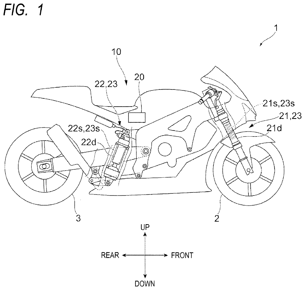
[0030]FIG. 1 is a diagram illustrating a schematic configuration of a motorcycle 1 according to a first embodiment.
[0031]The motorcycle 1, which is an example of a saddle-ride type vehicle, includes a front wheel 2, which is a wheel on the front side, a rear wheel 3, which is a wheel on the rear side, and a vehicle body 10.
[0032]In addition, the motorcycle 1 also includes a front fork 21 which connects the front wheel 2 and the vehicle body 10. The front fork 21 includes a suspension spring 21s which absorbs an impact applied to the front wheel 2 from a road surface or the like, and a damping device 21d which damps vibration of the suspension spring 21s.
[0033]In addition, the motorcycle 1 includes one rear suspension 22 for connecting the rear wheel 3 and the vehicle body 10 on each of the left side and the right side of the rear wheel 3. The rear suspension 22 includes a suspension spring 22s which absorbs an impact applied to the rear wheel 3 from a road surface or the like, and ...
second embodiment
[0124]FIG. 11 is a diagram showing a schematic configuration of a vehicle height adjustment device 2700 according to a second embodiment.
[0125]The vehicle height adjustment device 2700 of the second embodiment is different from the vehicle height adjustment device 700 of the first embodiment in that a suspension device 223 is provided instead of the suspension device 23 and a control device 220 is provided instead of the control device 20. The suspension device 223 is different from the suspension device 23 in that the suspension device 223 includes a switching unit 2800 instead of the switching unit 800. The control device 220 is different from the control device 20 in a switching control mode of a flow path of oil. Hereinafter, differences from the vehicle height adjustment device 700 will be described. Components having the same shape and function in the vehicle height adjustment device 2700 and the vehicle height adjustment device 700 are denoted by the same reference numerals, ...
third embodiment
[0141]FIG. 12 is a cross-sectional view of a screw pump 97.
[0142]A switching unit 3800 of a third embodiment is different in that the switching unit 3800 includes the screw pump 97 instead of the gear pump 93. Hereinafter, differences from the switching unit 800 of the first embodiment will be described. Components having the same shape and function in the switching unit 3800 and the switching unit 800 are denoted by the same reference numerals, and a detailed description thereof will be omitted.
[0143]The screw pump 97, which is an example of the second pump, includes a first screw 971 and a second screw 972 which rotates in accordance with the first screw 971. In addition, the screw pump 97 includes a housing body 973 which rotatably supports the first screw 971 and the second screw 972, respectively, and houses the first screw 971 and the second screw 972. The screw pump 97 further includes a motor 974 which drives the first screw 971.
[0144]The first screw 971 has a spiral blade 9...
PUM
 Abstract
Description
Claims
Application Information