Motor shaft state detection method, motor control method, motor shaft state detection device, motor control device, vehicle height adjustment device, saddle-type vehicle
- Summary
- Abstract
- Description
- Claims
- Application Information
AI Technical Summary
Benefits of technology
Problems solved by technology
Method used
Image

Examples
first embodiment
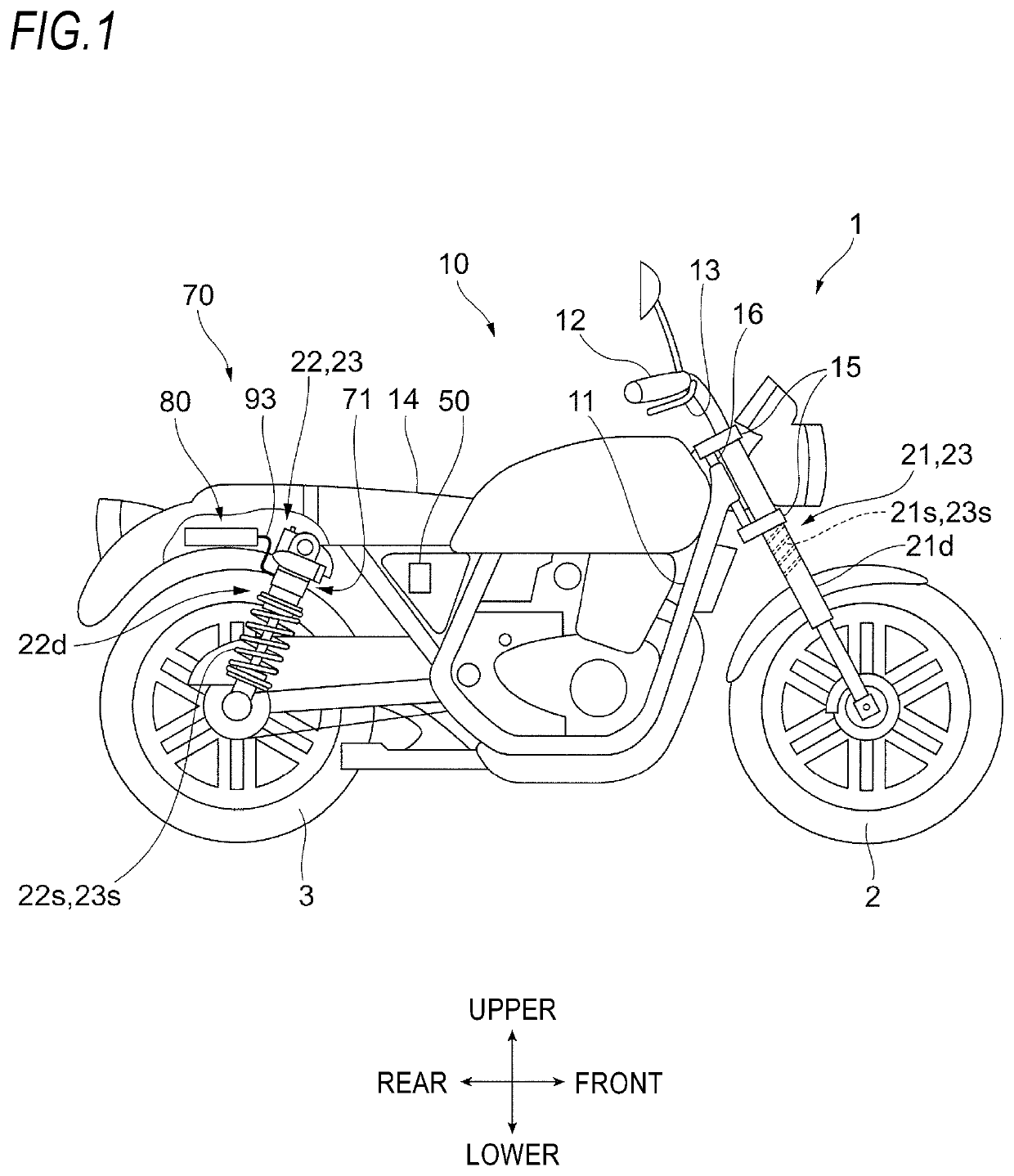
[0035]FIG. 1 shows an example of a schematic configuration of a two-wheeled motor vehicle 1 according to a first embodiment.
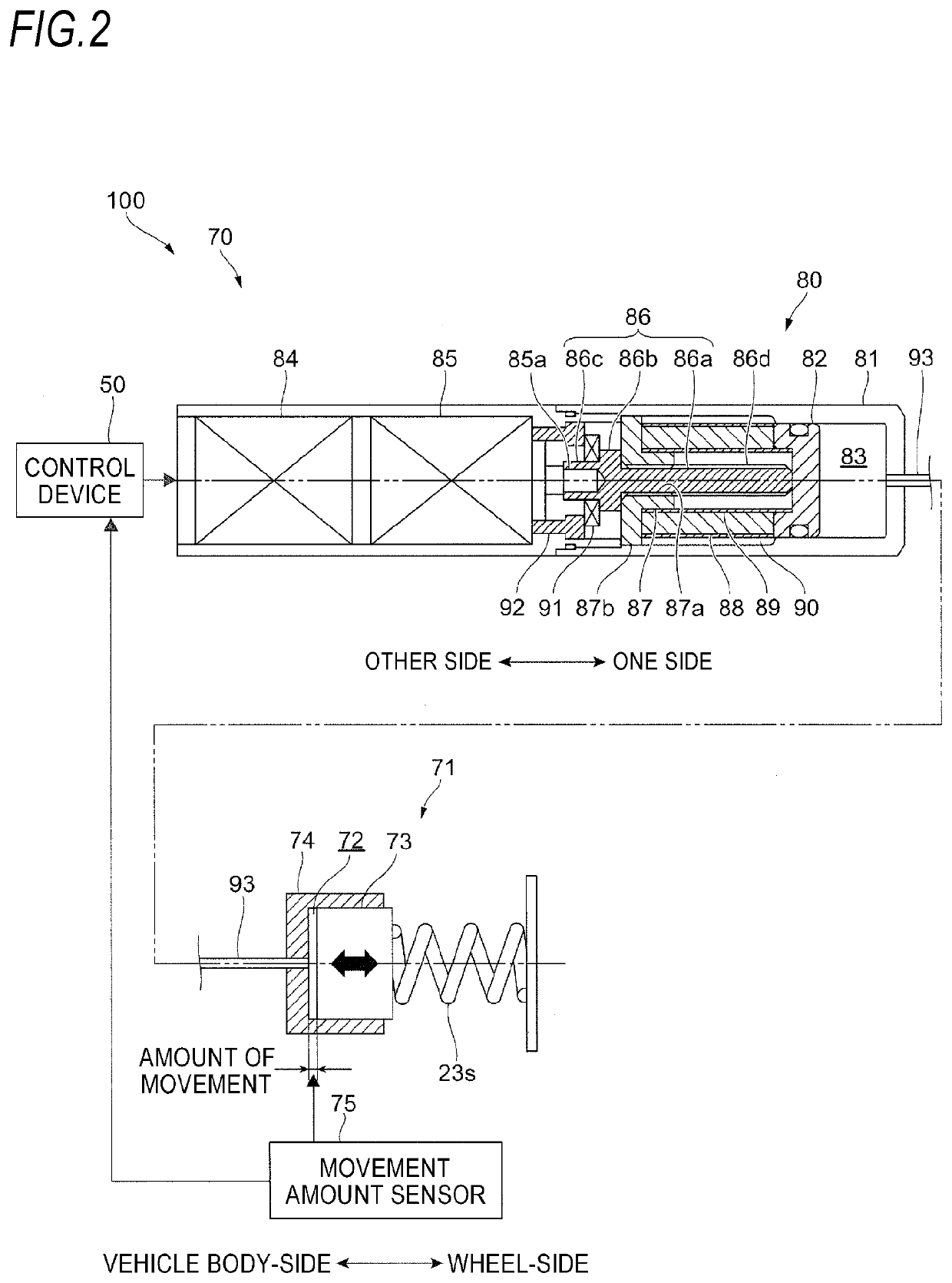
[0036]FIG. 2 shows an example of a schematic configuration of a vehicle height adjustment device 100.
[0037]The two-wheeled motor vehicle 1 as an example of the straddle-type vehicle has a front wheel 2, which is a wheel on a front side, and a rear wheel 3, which is a wheel on a rear side. In addition, the two-wheeled motor vehicle 1 includes a vehicle body frame 11 forming a skeleton of the two-wheeled motor vehicle 1, a handle 12, a brake lever 13, and a vehicle main body 10 having a seat 14. In descriptions below, the front wheel 2 and the rear wheel 3 may also be collectively referred to as ‘wheel’, and the vehicle main body 10 may also be referred to as ‘vehicle body’.
[0038]In addition, the two-wheeled motor vehicle 1 includes front forks 21 that are a first suspension device configured to connect the front wheel 2 and the vehicle body 10 each other. Furthe...
second embodiment
[0106]FIG. 9 is a flowchart showing an example of a procedure of setting processing according to a second embodiment, which is performed by the setting unit 51.
[0107]The setting processing according to the second embodiment is different from the setting processing according to the first embodiment described with reference to FIG. 4, with respect to a setting value of the target current It when the sensing unit 60 continuously senses the shaft locked state for a predetermined number of times. In the below, differences from the first embodiment are described. In the first embodiment and the second embodiment, the same processing is denoted with the same reference signs, and the detailed descriptions thereof are omitted. It may be exemplified that the predetermined number of times is two times.
[0108]First, the setting unit 51 decides whether the subtraction value ΔL(=Lt−La) is 0 (S401). When the subtraction value ΔL is not 0 (No in S401), the setting unit 51 decides whether the sensing...
third embodiment
[0114]FIG. 10 shows an example of a block diagram of a control device 250 according to a third embodiment.
[0115]The control device 250 according to the third embodiment is different from the control device 50 according to the first embodiment, in that it includes an estimation unit 270 configured to estimate an amount of movement of the support member 73 and a setting unit 251 corresponding to the setting unit 51 is configured to set the target current It by using the amount of movement estimated by the estimation unit 270. In the below, differences from the first embodiment are described. In the first embodiment and the third embodiment, the same parts are denoted with the same reference signs, and the detailed descriptions thereof are omitted.
[0116]The estimation unit 270 has a filter 271 configured to filter the motor current Im detected by the detection unit 54. The filter 271 is the same as the filter 611 and is configured to output a waveform R exemplified in FIG. 6, in which ...
PUM
 Abstract
Description
Claims
Application Information
 - Generate Ideas
- Intellectual Property
- Life Sciences
- Materials
- Tech Scout
- Unparalleled Data Quality
- Higher Quality Content
- 60% Fewer Hallucinations
Browse by: Latest US Patents, China's latest patents, Technical Efficacy Thesaurus, Application Domain, Technology Topic, Popular Technical Reports.
© 2025 PatSnap. All rights reserved.Legal|Privacy policy|Modern Slavery Act Transparency Statement|Sitemap|About US| Contact US: help@patsnap.com