Pressure sensor with improved strain gauge

Active Publication Date: 2019-03-14
SENSATA TECHNOLOGIES INC
View PDF12 Cites 5 Cited by
  • Summary
  • Abstract
  • Description
  • Claims
  • Application Information

AI Technical Summary

Benefits of technology

[0004]In light of the needs described above, in at least one aspect, there is a need for a cost effectiv

Problems solved by technology

However, inaccuracies tend to occur in typical MSGs in a number of ways.
Disparate ion accumulate across the resistors can lead to sensor signal drift.
Further,

Method used


Image

  • Pressure sensor with improved strain gauge
  • Pressure sensor with improved strain gauge
  • Pressure sensor with improved strain gauge

Examples


Example

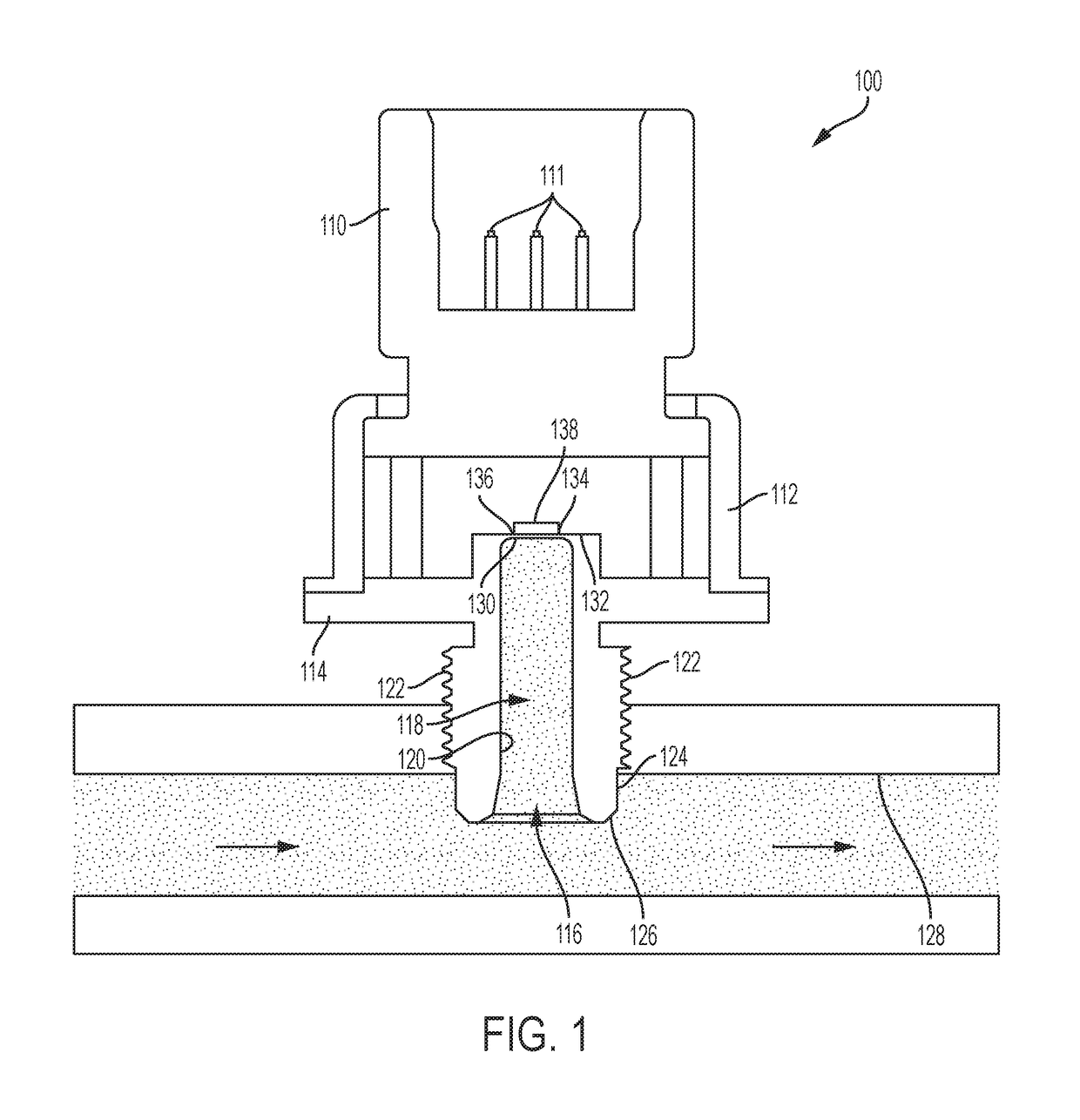
[0023]The subject technology overcomes many of the prior art problems associated with pressure sensors. In brief summary, the subject technology provides a pressure sensor and corresponding strain gauge that significantly reduce signal drift as compared to prior art sensors. The advantages, and other features of the systems and methods disclosed herein, will become more readily apparent to those having ordinary skill in the art from the following detailed description of certain preferred embodiments taken in conjunction with the drawings which set forth representative embodiments of the present invention. Like reference numerals are used herein to denote like parts. Further, words denoting orientation such as “upper”, “lower”, “distal”, and “proximate” are merely used to help describe the location of components with respect to one another. For example, an “upper” surface of a part is merely meant to describe a surface that is separate from the “lower” surface of that same part. No w...


PUM


Abstract

An apparatus senses a pressure of a fluid from a fluid medium. The apparatus has a port body with a peripheral wall surrounding an interior channel. The interior channel extends between a diaphragm on the port body and an opening for receiving the fluid. A strain gauge is disposed on the port body. The strain gauge has two or more resistors connected between input/output pads and ground pads. The resistors are spaced substantially equidistant from the ground pad to reduce mobile ion migration.

Description

FIELD OF THE INVENTION[0001]The subject disclosure relates to pressure sensing devices and more particularly to pressure sensors with improved strain gauge performance.BACKGROUND OF THE INVENTION[0002]Microfused silicon strain gauge (MSG) pressure sensors are widely used throughout a number of industries. In the automotive industry, MSGs are used for applications ranging from brake, transmission, and fuel pressure sensors, to occupant weight force sensing. Such pressure sensors typically include silicon strain gauge elements which are glass-bonded to a stainless steel diaphragm of a steel port body. Wheatstone bridge, or other strain gauge configurations are sometimes employed to yield a linear voltage output which is directly proportional to the applied pressure on the steel diaphragm by calibration.[0003]However, inaccuracies tend to occur in typical MSGs in a number of ways. For example, when temperature rises above 110 Celsius, chemical decomposition tends to occur within the gl...

Claims


Application Information

Patent Timeline
IPC IPC(8): G01L9/00
CPCG01L9/0055G01L9/0052G01L19/00G01L9/06G01L1/22G01L1/2262G01L1/2268G01L1/2287G01L9/0002G01L19/069G01L9/006G01L7/08
Inventor HUO, SHIHONGWOLF, ERIC A.PETRARCA, NEIL S.
Owner SENSATA TECHNOLOGIES INC
Why Eureka
Try Eureka