System for executing new instructions and method for executing new instructions
a new instruction and system technology, applied in the direction of instruments, computing, electric digital data processing, etc., can solve the problems of high cost, inability to implement the newly supported instructions of the subsequent generation processor, and a lot of work for the micro-architectur
- Summary
- Abstract
- Description
- Claims
- Application Information
AI Technical Summary
Benefits of technology
Problems solved by technology
Method used
Image
Examples
first embodiment
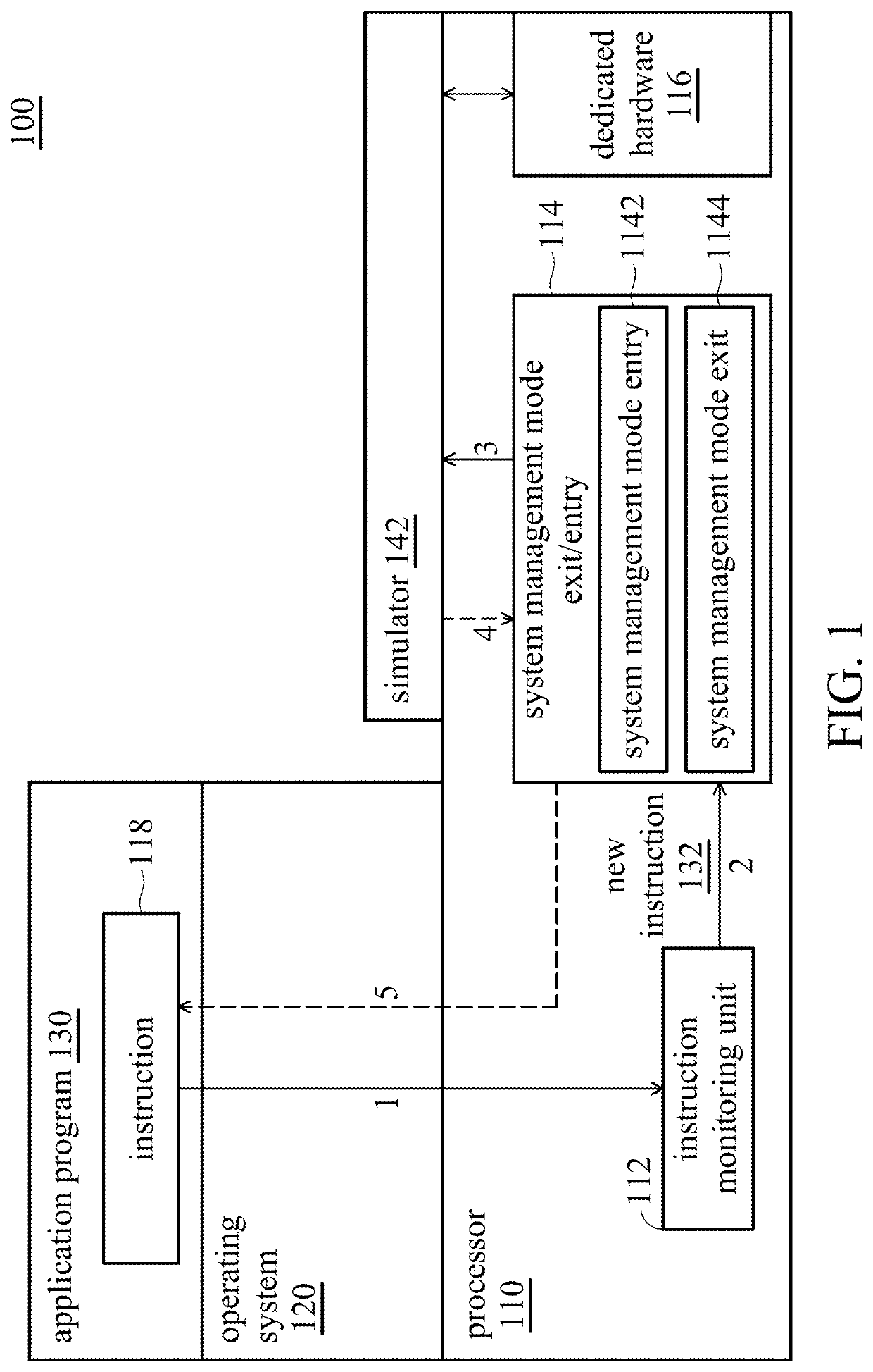
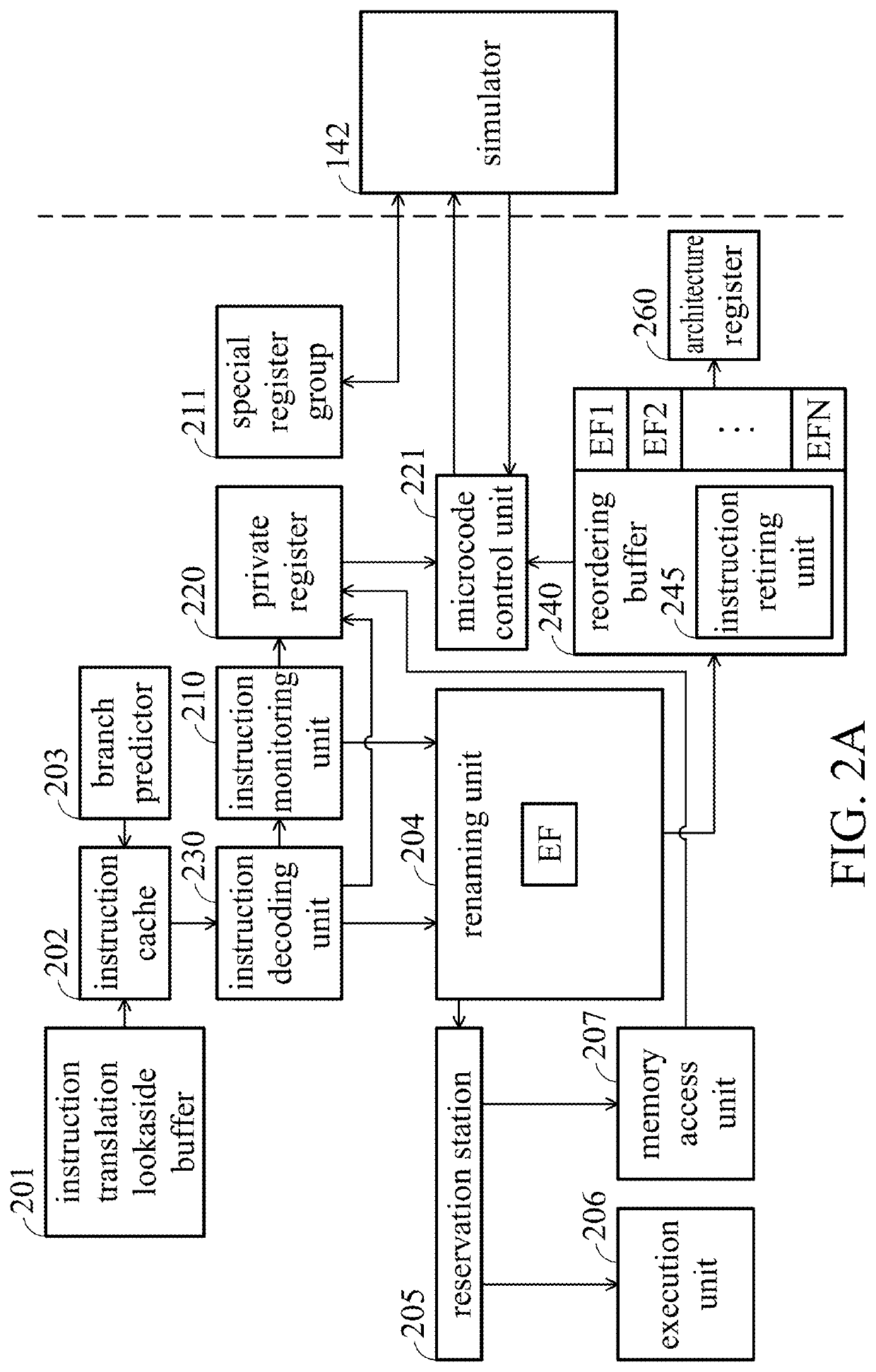
[0043]FIG. 2A is a block diagram of the processor in accordance with the first embodiment of the present disclosure. As shown in FIG. 2A, the part on the left of the dotted line is a structural diagram of the processor 110 shown in FIG. 1, and the simulator 142 on the right of the dotted line runs on the processor 110 in the system management mode. The following describes FIG. 2A with reference to FIG. 1.
[0044]As shown in FIG. 2A, the processor 110 includes an instruction translation lookaside buffer (ITLB) 201, an instruction cache 202, and a branch predictor 203. When the processor 110 executes an instruction of the application 130 or the operating system 120, the instruction translation lookaside buffer 201 of the processor 110 receives the address of the instruction. The branch predictor 203 is used to predict the conditional branch and transmit the branch prediction result to the instruction cache 202. The instruction cache 202 obtains the address of the received instruction fr...
second embodiment
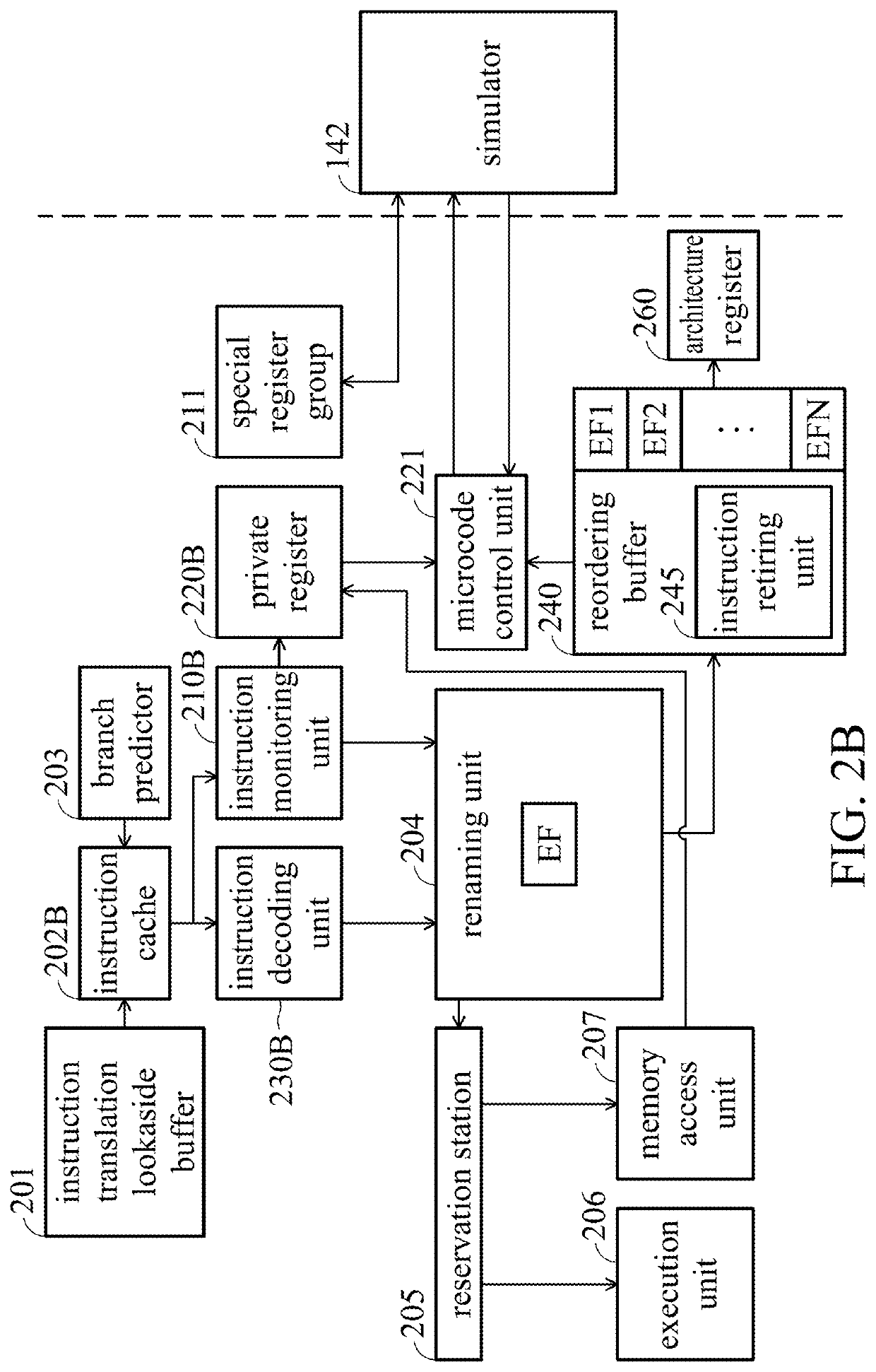
[0115]In the second embodiment, the processor 110 transmits the emulation flag to the pipeline, and the instruction monitoring unit determines whether the received instruction is a new instruction based on the machine code of the received instruction from the instruction cache. The second embodiment will be described below in conjunction with FIG. 2B, FIG. 2B1, and FIG. 3-7.
[0116]The functions of the modules with the same number in FIG. 2B as those of FIG. 2A are the same as the functions of the corresponding modules in FIG. 2A, and will not be repeated here. The following describes the difference between FIG. 2B of the second embodiment and FIG. 2A of the first embodiment.
[0117]As shown in FIG. 2B, the instruction monitoring unit 210B directly receives instructions from the instruction cache 202B. Then, the instruction monitoring unit 210B decodes the received instruction to generate decoding information. Then, the instruction monitoring unit 210B determines whether the received in...
third embodiment
[0121]In the third embodiment, the processor 110 does not pass the emulation flag into the pipeline. The instruction monitoring unit determines whether the received instruction is a new instruction based on the instruction information of the received instruction from the instruction decoding unit. The third embodiment will be described below in conjunction with FIG. 2C and FIGS. 3-7.
[0122]The functions of the modules with the same number in FIG. 2C as those of FIG. 2A are the same as those of the corresponding modules in FIG. 2A, and will not be repeated here. The difference between the third embodiment and the first embodiment is that, in the third embodiment, the instruction monitoring unit 210C does not send the emulation flag to the renaming unit 204C. The difference between FIG. 2C of the third embodiment and FIG. 2A of the first embodiment will be described in detail below.
[0123]As shown in FIG. 2C, the instruction monitoring unit 210C determines whether the received instructi...
PUM
 Abstract
Description
Claims
Application Information
 - R&D
- Intellectual Property
- Life Sciences
- Materials
- Tech Scout
- Unparalleled Data Quality
- Higher Quality Content
- 60% Fewer Hallucinations
Browse by: Latest US Patents, China's latest patents, Technical Efficacy Thesaurus, Application Domain, Technology Topic, Popular Technical Reports.
© 2025 PatSnap. All rights reserved.Legal|Privacy policy|Modern Slavery Act Transparency Statement|Sitemap|About US| Contact US: help@patsnap.com


