Machine learning model for identifying surfaces in a tubular

Pending Publication Date: 2022-07-07
DARKVISION TECH INC
View PDF0 Cites 0 Cited by
  • Summary
  • Abstract
  • Description
  • Claims
  • Application Information

AI Technical Summary

Benefits of technology

[0007]Further aspects of the invention are set out below and in the appended claims. Thus preferred embodiments of the invention enable t

Problems solved by technology

However, there are numerous errors in the logging process that need to be corrected to represent the surface smoothly.
This tends t

Method used


Image

  • Machine learning model for identifying surfaces in a tubular
  • Machine learning model for identifying surfaces in a tubular
  • Machine learning model for identifying surfaces in a tubular

Examples


Example

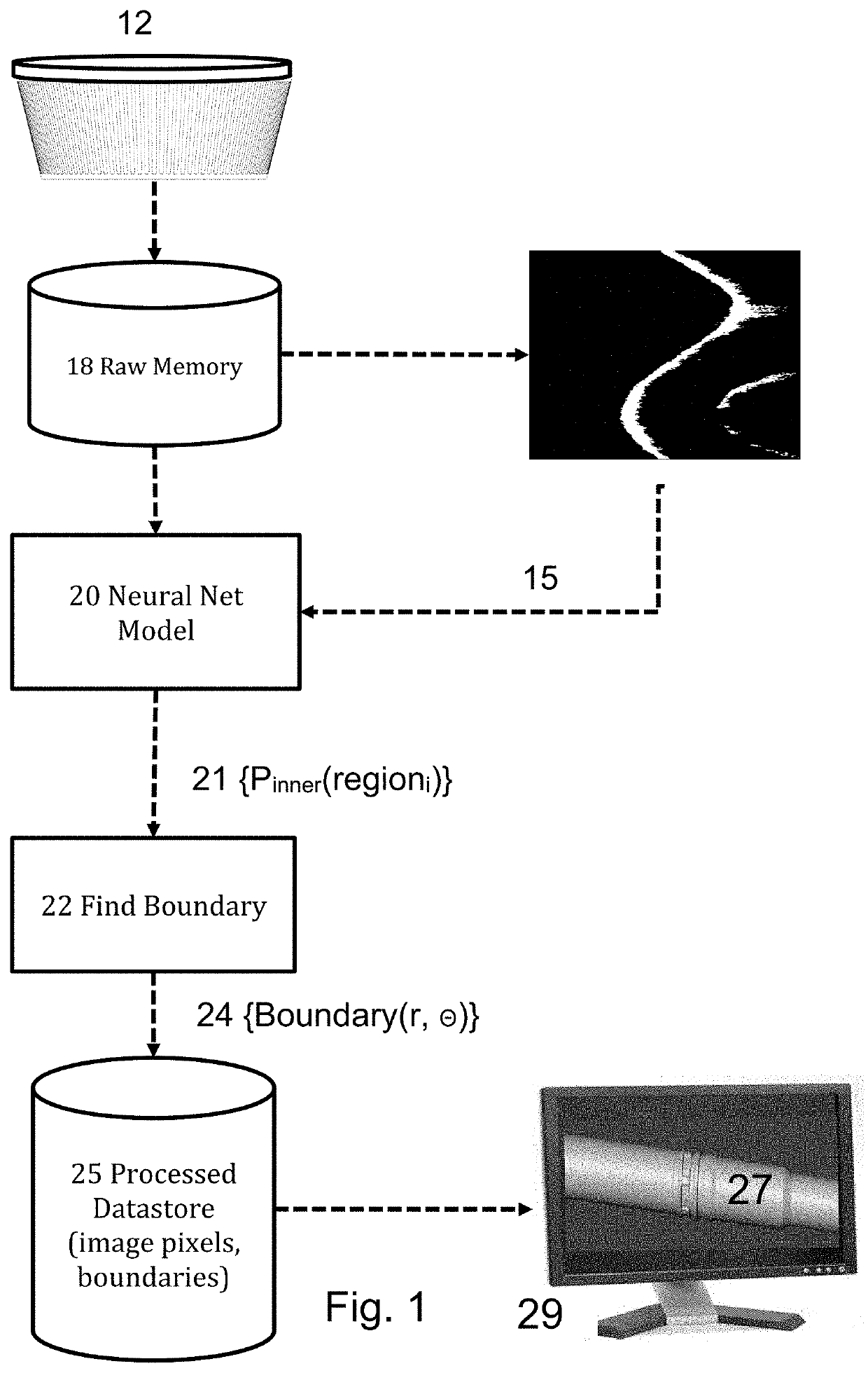
[0023]The present invention may be described by the following preferred embodiments with reference to the attached drawings. Disclosed are a method and system to automatedly identify image internal and external regions in a logged well from ultrasound images using a computer model. The model is a Machine Learning model. Advantageously, the present system may identify the tubular surface, i.e. the boundary between internal and external regions in the tubular, that are difficult for a human operator to trace. In difficult cases, the tubular surface might exhibit degrading features include glints, ringing, frequency changes, refraction, depth information, surfaces mating and materials affecting the speed of sound.

Radially Configured Sensors

[0024]The transducers are preferably a phased array operating in the ultrasound band. The present imaging tool is preferably that of the leading technology in this area, exemplified by: U.S. Pat. No. 10,781,690 filed 6 Oct. 2016 and entitled “Devices...


PUM


Abstract

A method and instruction memory for processing acoustic images of a tubular to determine the surface of the tubular. The images may be acquired by an acoustic logging tool deployed into a pipe or well. A Machine Learning model is trained to recognize regions of the acoustic images that are internal to the tubular or not, in order to determine surface pixels. The surface pixels may be rendered to create visualizations of the tubular where noise and non-surface features are filtered out automatically.

Description

RELATED APPLICATIONS[0001]This application claims priority to United Kingdom Patent Application Number 2100058.3, filed Jan. 4, 2021, the disclosure of which is incorporated herein by reference in its entirety.FIELD OF THE INVENTION[0002]The invention relates generally to inspection of fluid-carrying tubulars, in particular acoustic sensors detecting internal and external regions in oil and gas wells and pipelines.BACKGROUND OF THE INVENTION[0003]Cylindrical conduits such as well casings, tubulars and pipes may be imaged using ultrasound sensors mounted to a tool propelled through the conduit. Existing ultrasound tools comprise an array of piezoelectric elements distributed radially around the tool housing. The top surface of each element faces radially away from the tool towards the wall of the conduit. The reflected waves are received by the same elements and the pulse-echo time of the waves are used to deduce the distances to the internal and external walls and voids therebetween...

Claims


Application Information

Patent Timeline
IPC IPC(8): G06T7/00
CPCG06T7/0004G06T2207/20081G06T2207/20084G06T2207/20076G06T7/12G06T2207/10136E21B47/00E21B47/002G01N29/36G01N29/4445G01N29/4481G06T7/10G06T7/60G06T2207/10132G06T2207/20168G06T2207/30108
Inventor MAHMOUD, ANASKHALLAGHI, SIAVASH
Owner DARKVISION TECH INC
Why Eureka
Try Eureka