Material conveying apparatus with shut down valves

a technology of material conveying apparatus and shut-down valve, which is applied in the direction of conveyors, bulk conveyors, transportation and packaging, etc., can solve the problems of material plugging or pipeline blockage, low overall conveying pressure for a given mass flow rate,

Pending Publication Date: 2022-07-14
SCHENCK PROCESS EURO GMBH
View PDF40 Cites 1 Cited by
  • Summary
  • Abstract
  • Description
  • Claims
  • Application Information

AI Technical Summary

Problems solved by technology

In turn, this results in a lower overall conveying pressure for a given mass flow rate.
Conversely, a lower permeability implies a higher flow resistance, and may be associated with a greater degree of particle compaction and friction against the pipeline...

Method used


Image

  • Material conveying apparatus with shut down valves
  • Material conveying apparatus with shut down valves
  • Material conveying apparatus with shut down valves

Examples


Embodiment Construction

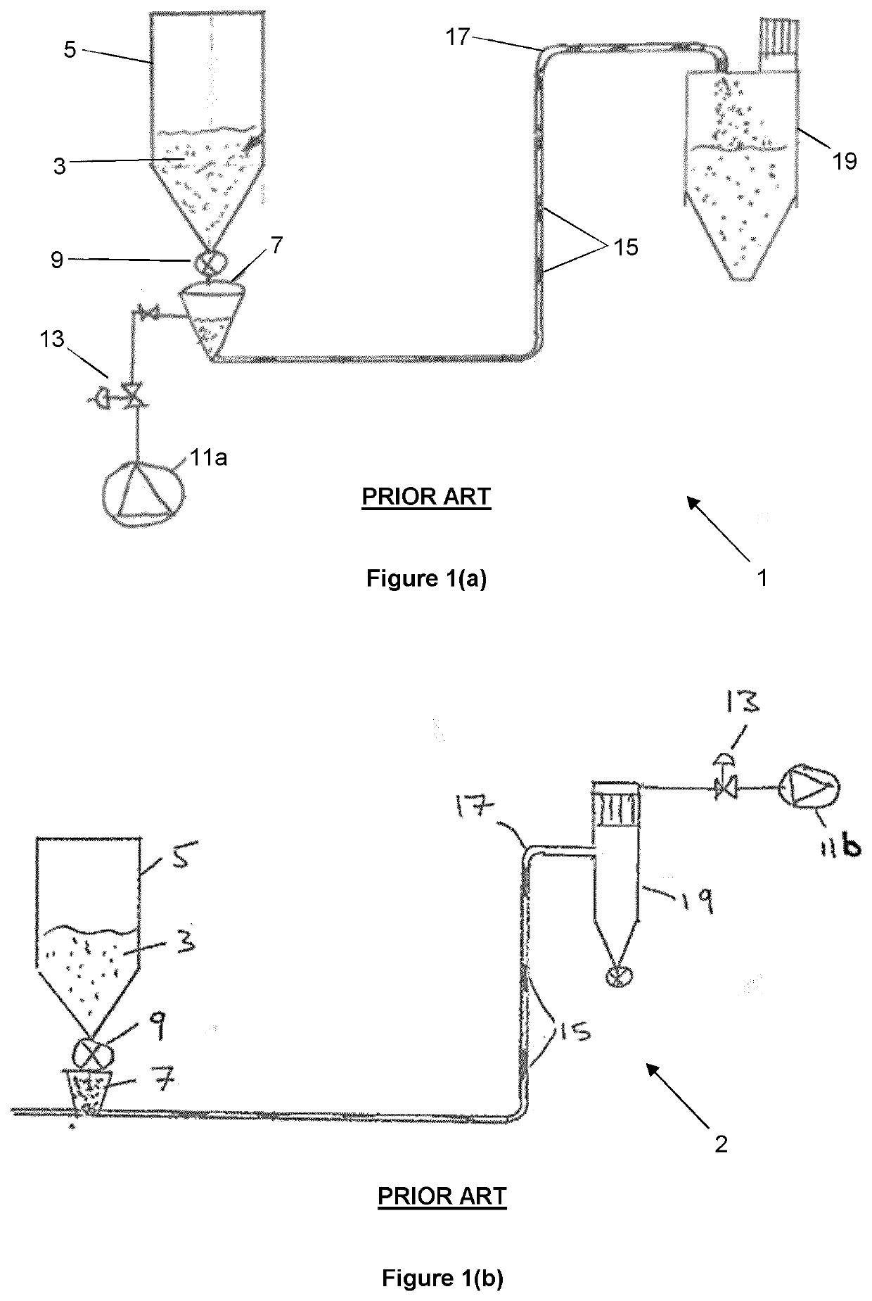
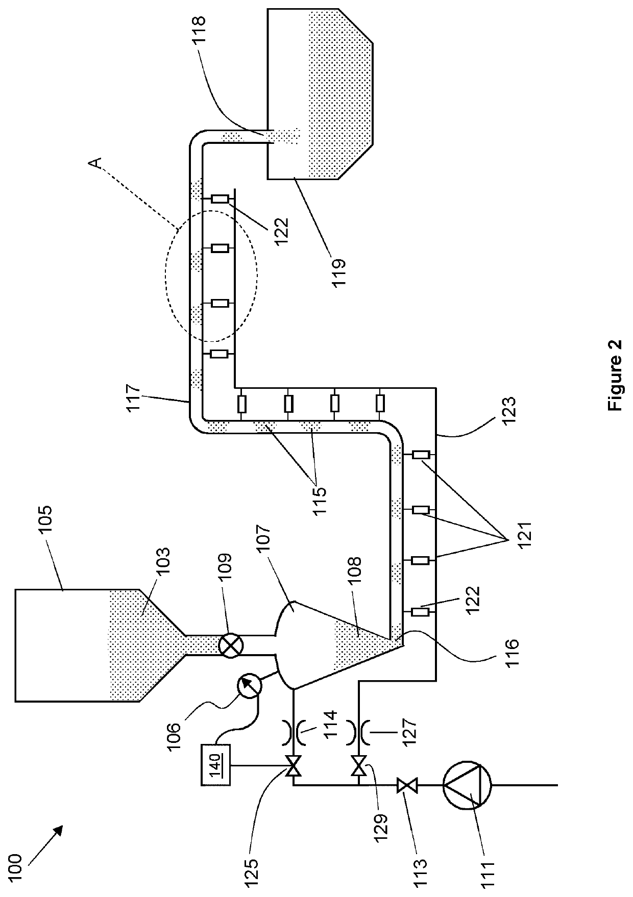
[0256]FIGS. 1(a) and (b) show a conventional dense phase pressurised and vacuum pneumatic conveying systems 1 and 2, as described above. FIG. 2 shows an embodiment of a system 100 for conveying particulate material in accordance with the invention. Features in common with the systems 1 and 2 are provided with like reference numerals, incremented by 100.

[0257]The system 100 has a transporter apparatus 107, for delivering a quantity of particulate material 108 into an inlet 116 of the conveying pipeline 117. Particulate material 103 is received into the transporter apparatus 107 from a hopper 105 positioned above the transporter apparatus, via a material shut-off valve 109. The transporter apparatus 107 is pressurised to a system pressure of conveying gas (in the present embodiment, compressed air) which is fed from a compressor 111 via conduit 112. The system 100 is typically coupled to a plant compressed air supply (of which the compressor 111 forms a part). The pressure of compress...


PUM


Abstract

Disclosed is a system and method for conveying particulate material. A plurality of injector arrangements are arranged along the conveying pipeline, for injecting a continuous flow of conveying gas into the pipeline. Each injector arrangement is operable to increase the flow rate at which conveying gas is injected into the pipeline on of pressure conditions in the conveying pipeline indicative of locally decreased material permeability. Each injector arrangement comprises a piloted shut-off valve positioned between the flow rate adjustment arrangement and the conveying pipeline and operable to close in response to a received pilot signal indicative of a pressure condition in the conveying pipeline below a lower threshold pressure condition. The continuous flow of conveying gas injected by each of the injector arrangements prevents particulate material from entering any part of the injector arrangements, thereby reducing the risk of blockage of nozzles, injection pathway selection valves and the like. The continuous injection of conveying gas along the pipeline also maintains a degree of permeability particulate material in the pipeline and promotes stable conveying. The piloted shut-off valve of each injector arrangement is operable to independently detect a large pressure drop in the pipeline, and to close in order to store pressurised conveying gas in the injector arrangement and supply thereto.

Description

FIELD OF THE INVENTION[0001]The invention relates to apparatus and methods for conveying particulate material through a pipeline, and in particular to the use of pressurisation or vacuum techniques to convey dense phase particulate material.BACKGROUND TO THE INVENTION[0002]Pneumatic conveying by pressure or vacuum are techniques employed to transport particulate materials along a pipeline. These techniques are typically employed to transport materials over distances typically in the range from 10 m to 500 m, and in some cases even further. Pneumatic conveying avoids the need for the use of conveyor belts or the like, which can be bulky and costly to maintain.[0003]Pneumatic conveying techniques are particularly useful where material has to be transported along a complex path, or to multiple delivery points. These techniques also ensure that the particulate material can be entirely contained within a pipeline, which may avoid the need to deal with dust from or contamination of the ma...

Claims


Application Information

Patent Timeline
IPC IPC(8): B65G53/52B65G53/58B65G53/66
CPCB65G53/526B65G53/66B65G53/58
Inventor ELLIS, RICHARD
Owner SCHENCK PROCESS EURO GMBH
Why Eureka
Try Eureka