Jet nozzle equipped with a thermally regulated ring

a technology of thermal regulation and nozzle, which is applied in the direction of rocket engine plants, machines/engines, engine fuctions, etc., can solve the problems of not allowing cooling of elements present in the vicinity of the downstream end of the chamber such as the annular flange, and the annular flange is exposed to very high temperatures, so as to facilitate the radial centering of the divergent

Pending Publication Date: 2022-07-14
ARIANEGRP SAS
View PDF5 Cites 0 Cited by
  • Summary
  • Abstract
  • Description
  • Claims
  • Application Information

AI Technical Summary

Benefits of technology

[0007]By cooling the connection between the combustion chamber and the divergent directly at the intermediate ring, the latter is protected from the heat emitted by the divergent, which improves the reliability of the connection between the combustion chamber and the divergent. It is thus possible to envisage a use of the nozzle with high combustion temperatures while being able to use relatively inexpensive materials for the production of the intermediate ring. In addition, this cooling solution simplifies the geometry of the combustion chamber at its downstream end allowing envisaging a connection with different types of divergents.
[0008]According to one particular aspect of the nozzle according to the invention, a heat transfer fluid circulates in said at least one inner channel of the intermediate ring. The ring and the connection made thereby are cooled by means of a cooling circuit independent of that of the combustion chamber. The flow rate and the nature of the heat transfer fluid can therefore be chosen in order to obtain the best thermal regulation. This independent cooling circuit can further be used after shutdown of the rocket engine to mitigate the heating effects due to the phenomenon called “heat soak back” which corresponds to the heating after operation of some elements by others having a high thermal inertia.
[0009]According to one particular characteristic, the inner channel(s) of the intermediate ring have a geometry able to create swirls in the heat transfer fluid. This allows increasing the heat exchanges and consequently the cooling of the ring and surrounding portions.
[0010]According to another particular aspect of the nozzle according to the invention, a phase change material is present in said at least one inner channel of the intermediate ring. In this case, the thermal transfer (cooling) is made by latent heat, the phase change material being able to store the energy by a simple change of state while maintaining a temperature constant. The ring and the connection made thereby are maintained at acceptable temperature levels and independently of the cooling circuit of the combustion chamber. The properties of the phase change material can be defined based on the only need for cooling at the intermediate ring. The cooling made by the phase change material can further be used after shutdown of the rocket engine to mitigate the heating effects due to the phenomenon called “heat soak back” which corresponds to the heating after operation of some elements by others having a high thermal inertia.
[0012]According to yet another aspect of the nozzle of the invention, the downstream flange of the intermediate ring includes support lugs, said lugs cooperating with one or more shoulders present on the upstream end of the divergent. The heat exchange surfaces between the divergent and the ring are thus limited by minimizing the contact surface between these two elements.
[0013]According to one particular characteristic of this connecting mode, the intermediate ring comprises, on its face opposite the wall of the divergent, bosses spaced from each other along a circumferential direction. This facilitates the radial centering of the divergent on the intermediate ring.

Problems solved by technology

However, the solution consisting in providing the downstream end of the combustion chamber with a cooling circuit complicates the production of the combustion chamber as well as the geometry of the annular flange for fixing the divergent to the chamber.
Furthermore, while the cooling circuit integrated into the combustion chamber allows effectively regulating the temperature of said chamber, it does not allow cooling the elements present in the vicinity of the downstream end of the chamber such as the annular flange.
However, the annular flange is exposed to very high temperatures due to its proximity to the divergent.
Consequently, the annular flange must be capable of withstanding high temperatures, which involves the use of expensive materials.

Method used


Image

  • Jet nozzle equipped with a thermally regulated ring
  • Jet nozzle equipped with a thermally regulated ring
  • Jet nozzle equipped with a thermally regulated ring

Examples


Embodiment Construction

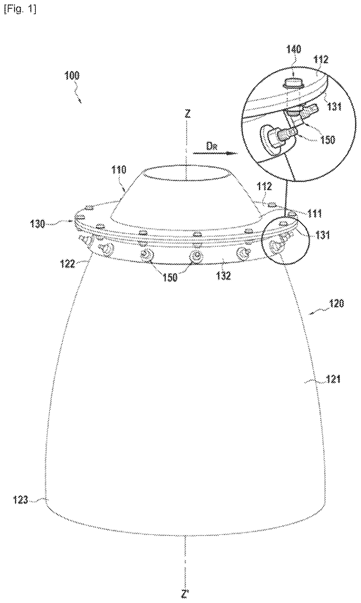
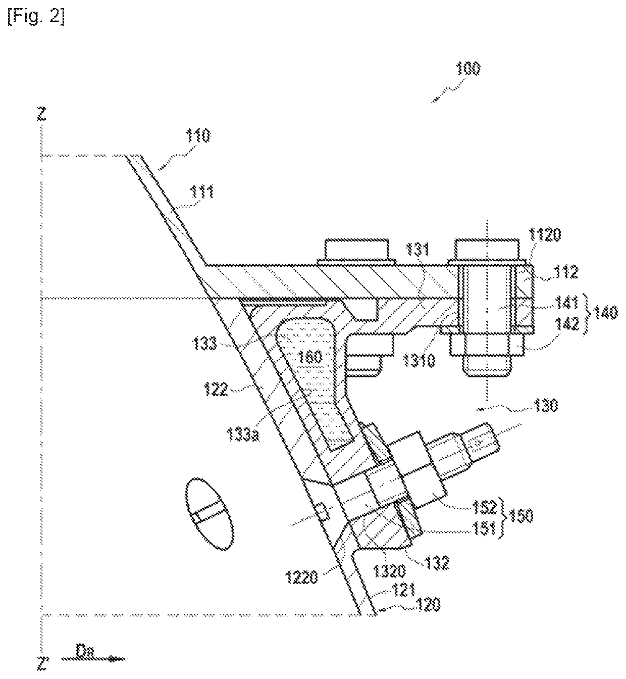
[0021]FIGS. 1 and 2 illustrate a rocket engine nozzle 100 in accordance with one embodiment of the invention. The nozzle 10 of longitudinal axis ZZ′ comprises a combustion chamber made of metallic material 110 having a downstream end 111 and a divergent 120 formed of a cone-shaped wall 121 extending between an upstream end 122 and a downstream end 123, the upstream end 122 of the divergent 120 being connected to the downstream end 111 of the combustion chamber 110. The combustion chamber 110 further comprises a cooling circuit allowing circulating a coolant on the wall of the chamber (not represented in FIGS. 1 and 2) as it is the case in particular of a combustion chamber called regeneration combustion chamber.

[0022]In accordance with the invention, the nozzle 100 further comprises an intermediate ring 130 which ensures the connection between the combustion chamber 110 and the divergent 120. The intermediate ring 130 comprises an upstream flange 131 which extends along a radial dir...


PUM


Abstract

A nozzle comprises a combustion chamber having a downstream end and a divergent formed of a cone-shaped wall extending between an upstream end and a downstream end. The upstream end of the divergent is connected to the downstream end of the combustion chamber by an intermediate ring having an upstream flange fixed on a fixing flange secured to the combustion chamber and a downstream flange connected to the upstream end of the divergent. The intermediate ring having an inner channel present between the upstream and downstream flanges of the intermediate ring. A material able to take heat from the ring is present in the inner channel.

Description

TECHNICAL FIELD[0001]The present invention relates to a rocket engine nozzle comprising a combustion chamber and a divergent formed of a cone-shaped wall, the divergent being connected to the downstream end of the combustion chamber by a flange or a ring.Prior art[0002]Document WO 2018 / 002523 discloses a nozzle comprising a combustion chamber made of metallic material having a downstream end and a divergent made of composite material formed of a cone-shaped wall and whose upstream end of the divergent made of composite material is connected to the downstream end of the combustion chamber by an annular flange made of metallic material. The downstream end of the combustion chamber is provided with a cooling circuit for reducing the temperature in the area of the combustion chamber where the axial fixation with the divergent is made.[0003]However, the solution consisting in providing the downstream end of the combustion chamber with a cooling circuit complicates the production of the c...

Claims


Application Information

Patent Timeline
Patent Type & Authority Applications(United States)
IPC IPC(8): F02K9/97F02K9/64
CPCF02K9/972F02K9/64F05D2260/31F05D2300/603F05D2300/10F05D2260/207F05D2260/2212F02K9/97
Inventor ZORRILLA, XAVIERLASSENAY, FLORIAN
Owner ARIANEGRP SAS
Why Eureka
Try Eureka