Thermal management system, powertrain, and vehicle

a technology of management system and powertrain, applied in the direction of electric propulsion mounting, machines/engines, transportation and packaging, etc., can solve the problems of significantly lower heat generation amount, insufficient occupant compartment heating of ash heat generated by internal combustion engines, and poor energy efficiency of internal combustion engines at lower power output levels. achieve better energy efficiency at higher power output levels, and poor energy efficiency of internal combustion engines

Pending Publication Date: 2022-07-28
SCANIA CV AB
View PDF0 Cites 1 Cited by
  • Summary
  • Abstract
  • Description
  • Claims
  • Application Information

AI Technical Summary

Problems solved by technology

Moreover, these types of engines have become increasingly energy efficient meaning that the waste heat generated by the internal combustion engine may be insufficient for heating the occupant compartment to a desired level with a traditional heating arrangement.
However, the amount of heat generated is significantly lower than what is generated by an internal combustion engine.
Generally, an internal combustion engine has poor energy efficiency at lower power output levels and better energy efficiency at higher power output levels.
An electric propulsion system usually has great energy efficiency at low power output levels and at high power output levels, but the storage of electric energy in the vehicle is usually insufficient for allowing longer time periods of operation at higher power output levels.
As understood from the above, in many cases, the waste heat generated by a hybrid electric propulsion system can be insufficient for heating the occupant compartment of the vehicle.
Such a start-up of the internal combustion engine increases the consumption of fuel and increases emissions from the propulsion system.
However, as is the case with several other types of systems, a heat pump circuit has a narrow operational range in which it operates most efficiently and seasonal changes, temperature variations, and variations in heating demand of the occupant compartment put limitations on the efficiency of such a system.
Moreover, seasonal changes, temperature variations, and variations in heating demand of the occupant compartment put different requirements on such a system, which can be conflicting requirements.

Method used


Image

  • Thermal management system, powertrain, and vehicle
  • Thermal management system, powertrain, and vehicle
  • Thermal management system, powertrain, and vehicle

Examples


Embodiment Construction

[0055]Aspects of the present invention will now be described more fully. Like numbers refer to like elements throughout. Well-known functions or constructions will not necessarily be described in detail for brevity and / or clarity.

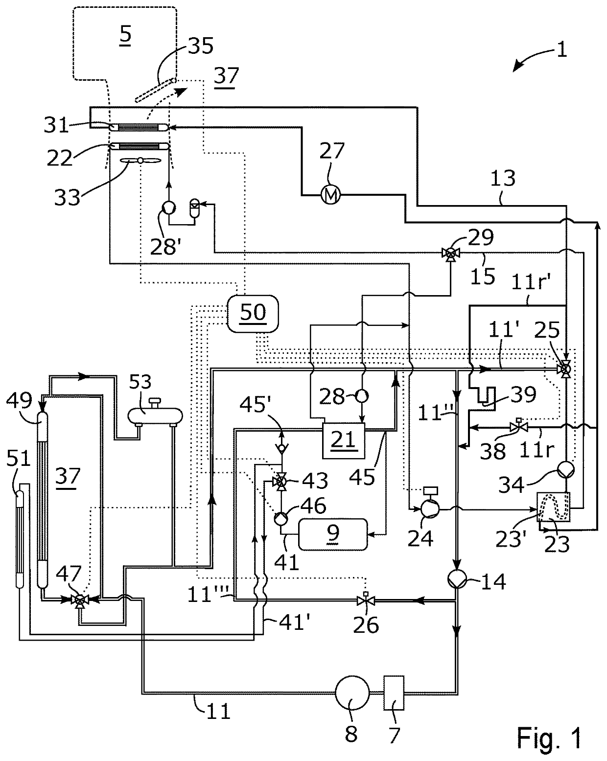
[0056]FIG. 1 schematically illustrates a thermal management system 1 according to some embodiments. The thermal management system 1 is configured to control transfer of heat in a vehicle, wherein the vehicle comprises an occupant compartment 5 and a propulsion system 7, 8, 9 configured to provide motive power to the vehicle. The occupant compartment 5 is configured to accommodate one or more occupants. The thermal management system 1 is in some places herein referred to as “the system 1” for the reason of brevity and clarity. According to the illustrated embodiments, propulsion system 7, 8, 9 is an electric propulsion system 7, 8, 9 comprising power electronics 7, an electric machine 8, and a battery 9. The electric machine 8 is configured to provide motive...


PUM


Abstract

A thermal management system for a vehicle is disclosed, wherein the vehicle comprises an occupant compartment and a propulsion system configured to provide motive power to the vehicle. The system comprises a propulsion coolant circuit configured to cool at least a portion of the propulsion system, a heating circuit configured to heat the occupant compartment, and a heat pump circuit comprising a first evaporator in the propulsion coolant circuit and a condenser in the heating circuit. The propulsion coolant circuit comprises a connecting conduit connecting the propulsion coolant circuit to the heating circuit at a position upstream of the condenser, and a first valve configured to control flow of coolant through the connecting conduit. The present disclosure further relates to a powertrain for a vehicle, as well as a vehicle.

Description

CROSS-REFERENCE TO RELATED APPLICATIONS[0001]This application is a National Stage Patent Application (filed under 35 § U.S.C. 371) of PCT / SE2020 / 050600, filed Jun. 10, 2020 of the same title, which, in turn claims priority to Swedish Patent Application No. 1950848-0 filed Jul. 5, 2019 of the same title; the contents of each of which are hereby incorporated by reference.FIELD OF THE INVENTION[0002]The present disclosure relates to a thermal management system for a vehicle. The present disclosure further relates to a powertrain for a vehicle, as well as a vehicle comprising a powertrain.BACKGROUND OF THE INVENTION[0003]Vehicles with an occupant compartment usually comprise a heating arrangement for heating the occupant compartment utilizing waste heat of a propulsion system of the vehicle. Due to environmental concerns, as well as economic concerns of customers, propulsion systems of modern vehicles have become more energy efficient meaning that less waste heat is available for heatin...

Claims


Application Information

Patent Timeline
Patent Type & Authority Applications(United States)
IPC IPC(8): B60H1/00B60H1/14
CPCB60H1/00899B60H2001/00307B60H1/00385B60H1/143B60H1/00278B60H2001/00949B60H2001/00928F01P2060/14F01P2060/08F01P3/20F01P2050/24F01P7/165B60K11/02B60K2001/003B60K2001/005B60K2001/006B60K1/00Y02T10/70B60H1/32284B60H1/04
Inventor HALL, OLAMOHLIN, MARTINKARDOS, ZOLTANERIKSSON, RICKARD
Owner SCANIA CV AB
Why Eureka
Try Eureka