Spinning device having a floating spinning ring and balloon limiter tube

a technology of limiter tube and spinning ring, which is applied in the direction of spinning machine, continuous wounding machine, paper machine, etc., can solve the problems of balloon collapse or fold, thread breakage, and interruption of spinning process

Active Publication Date: 2022-07-28
SAURER SPINNING SOLUTIONS GMBH & CO KG
View PDF10 Cites 0 Cited by
  • Summary
  • Abstract
  • Description
  • Claims
  • Application Information

AI Technical Summary

Problems solved by technology

However, the higher spindle speeds in comparison with spinning machines having ring traveller systems result in an enlarged thread balloon, and this increases the risk that the thread balloon collapses or folds up, leading ultimately to a thread break and to an interruption of the spinning process.
Furthermore, the higher spindle speeds also lead to increased centrifugal forces acting on the yarn.
These increased centrifugal forces can lead to tearing of the yarn, whic...

Method used


Image

  • Spinning device having a floating spinning ring and balloon limiter tube
  • Spinning device having a floating spinning ring and balloon limiter tube
  • Spinning device having a floating spinning ring and balloon limiter tube

Examples


Embodiment Construction

[0062]The following description of the embodiments of the present invention is merely exemplary in nature and is in no way intended to limit the invention, its application, or uses. The following description is provided herein solely by way of example for purposes of providing an enabling disclosure of the invention, but does not limit the scope or substance of the invention.

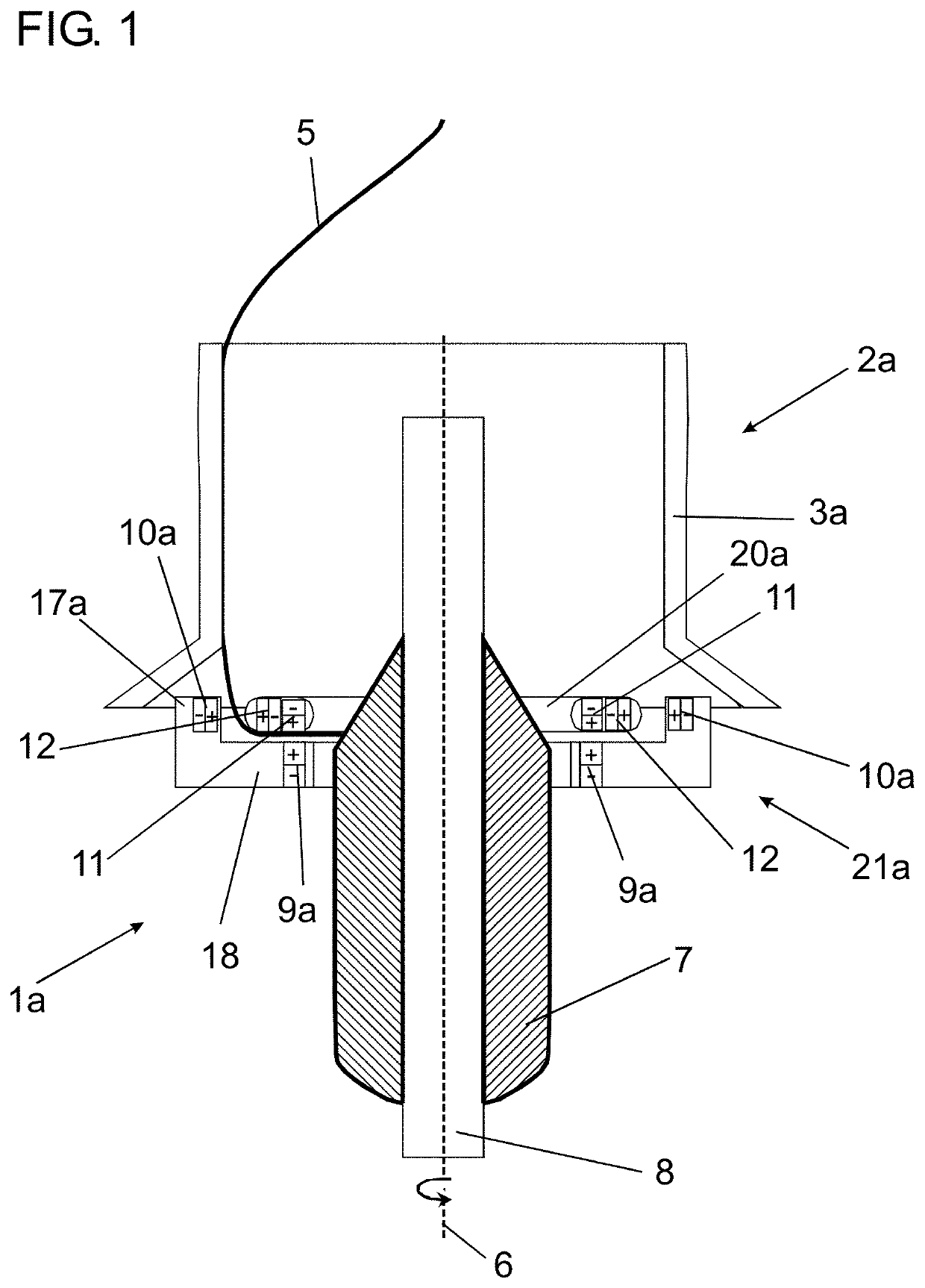
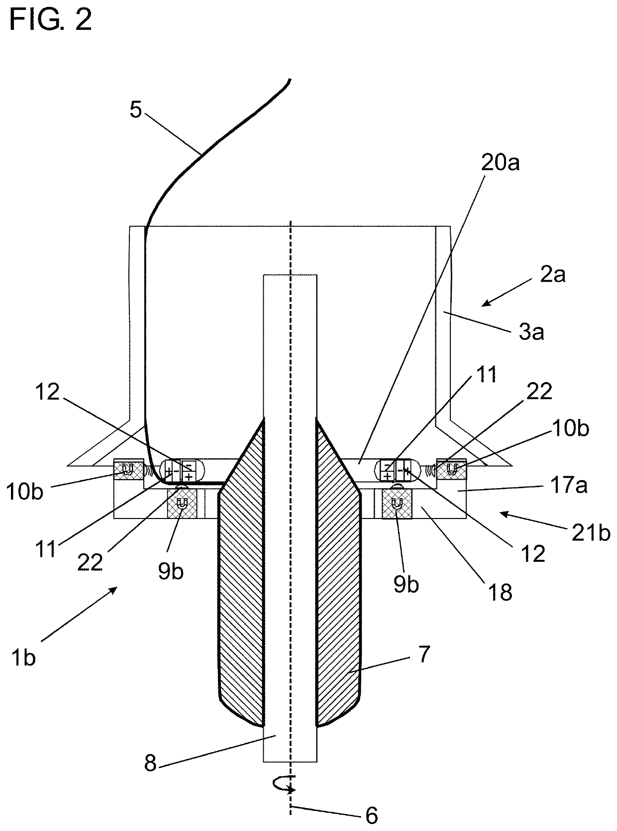
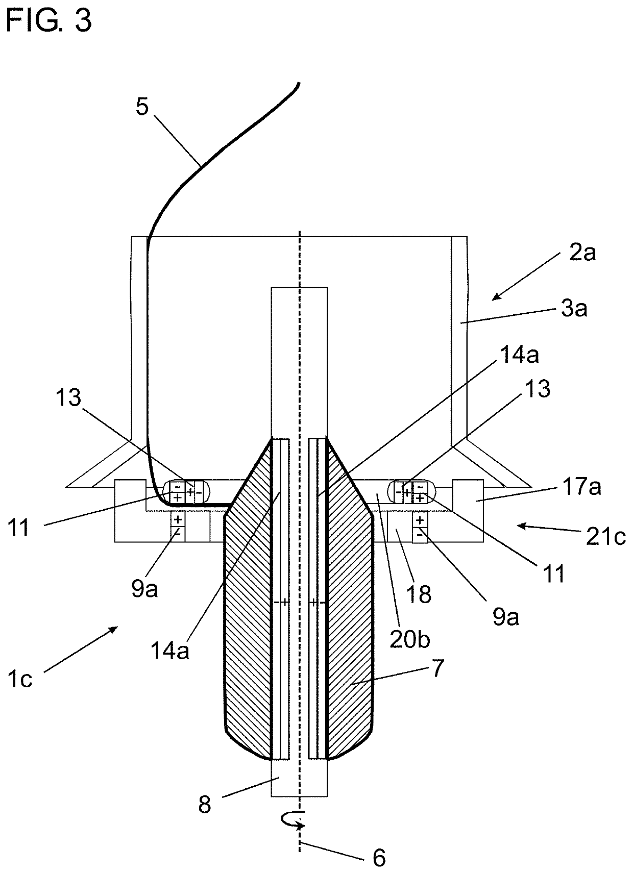
[0063]A first embodiment of a spinning device 1a is shown in a schematic illustration in FIG. 1. In the spinning device 1a, a yarn 5 fed from a drafting system (not shown here) reaches a yarn tube 8, which is arranged on a spindle axis 6 and on which the yarn 5 is deposited as a yarn winding 7. In order to guide the yarn 5 through the spinning device 1a, the spinning device 1a has a spinning-ring guiding unit 21a and a balloon limiter tube 2a, which consists of a first tube body 3, the spinning-ring guiding unit 21a and the balloon limiter tube 2a each being arranged coaxial with the spindle axis 6.

[0064]In the ...


PUM


Abstract

A spinning device, for a ring spinning or ring twisting machine, having a spinning spindle for holding a yarn tube such that the yarn tube is oriented coaxial with a spindle axis, a spinning ring for guiding, on the outside thereof, a yarn to be wound on the yarn tube, the spinning ring being arranged coaxial with the spindle axis, and a spinning-ring guiding unit arranged coaxial with the spindle axis, wherein the spinning ring is floatingly fixed at the spinning-ring guiding unit in the spindle-axis direction. In order to provide a spinning device and a spinning machine having a spinning device which allow a spinning process to be reliably performed without limitation of the spindle speed and without use of a ring traveller, a balloon limiter tube is arranged coaxial with the spindle axis such that the yarn is guided on an inner face of the balloon limiter tube.

Description

CROSS-REFERENCE TO RELATED APPLICATION[0001]This application claims priority from German National Patent Application No. DE 10 2021 101 435.2, filed Jan. 22, 2021, entitled “Spinneinrichtung mit schwebendem Spinnring and Ballonbegrenzerhülse”, the entire contents of which are incorporated herein by reference.FIELD OF THE INVENTION[0002]The invention relates to a spinning machine, more particularly a ring spinning or ring twisting machine, comprising a spinning device for producing a yarn and winding the yarn on a yarn tube, and to a spinning device, more particularly for a ring spinning or ring twisting machine, comprising: a spinning spindle for holding a yarn tube such that the yarn tube is oriented coaxial with a spindle axis; a spinning ring for guiding, on the outside thereof, a yarn to be wound on the yarn tube, the spinning ring being arranged coaxial with the spindle axis; and a spinning-ring guiding unit arranged coaxial with the spindle axis, wherein the spinning ring is f...

Claims


Application Information

Patent Timeline
IPC IPC(8): D01H7/56D01H7/58D01H7/64D01H1/42
CPCD01H7/56D01H1/427D01H7/64D01H7/58
Inventor KUEPPERS, SIMON
Owner SAURER SPINNING SOLUTIONS GMBH & CO KG
Why Eureka
Try Eureka