Silking machine spindle assembly, silking machine and method for balancing dynamic unbalance of silking machine

A laying machine and spindle technology, applied in the field of steel rolling machinery, can solve problems such as large vibration, and achieve the effects of reduced vibration, increased spindle speed, and fast balance configuration.

Active Publication Date: 2015-02-25
CISDI ENG CO LTD
View PDF3 Cites 0 Cited by
  • Summary
  • Abstract
  • Description
  • Claims
  • Application Information

AI Technical Summary

Problems solved by technology

[0005] In view of this, the purpose of the present invention is to provide a method for balancing the unbalanced spinning machine, a spinning machine spindle assembly and a spinning machine, so as to solve the problems caused by the eccentricity of the existing spinning machine. The disadvantage of large vibration, and then increase the operating speed of the laying machine

Method used


Image

  • Silking machine spindle assembly, silking machine and method for balancing dynamic unbalance of silking machine
  • Silking machine spindle assembly, silking machine and method for balancing dynamic unbalance of silking machine
  • Silking machine spindle assembly, silking machine and method for balancing dynamic unbalance of silking machine

Examples


Embodiment Construction

[0024] The present invention will be further described below in conjunction with the accompanying drawings and embodiments.

[0025] As shown in the figure, the method for balancing the unbalanced spinning machine in this embodiment includes the following steps:

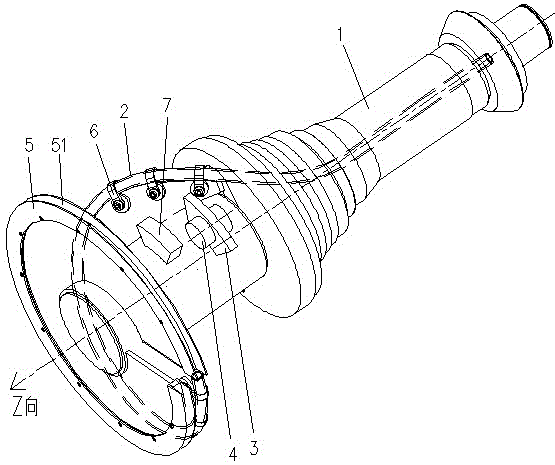
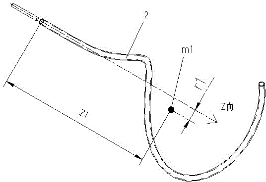
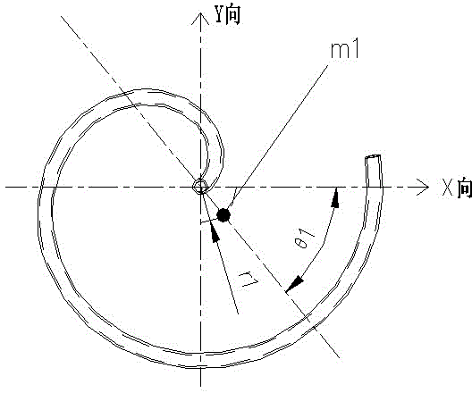
[0026] a. Establish a three-dimensional cylindrical coordinate system with the Z-axis of the three-dimensional coordinates on the axis line of the main shaft 1 of the laying machine, and use r to represent the radial distance coordinates from the midpoint of the three-dimensional cylindrical coordinate system to the Z axis, and use θ to represent the three-dimensional cylindrical coordinate system The azimuth coordinates of the midpoint, and represent the coordinates of the midpoint of the three-dimensional cylindrical coordinate system in the Z-axis direction with z, find out the coordinate position of the centroid of the spinning pipe 2 in the three-dimensional cylindrical coordinate system, and calculate the centro...


PUM


Abstract

A method for balancing a dynamic imbalance in a strand laying head, a strand laying head main shaft component, and a strand laying head. The strand laying head main shaft component comprises a main shaft (1) and a strand laying tube (2) fixed on the main shaft. A strand laying tube balancing block (3) for balancing eccentric quality of the strand laying tube is disposed on the strand laying head main shaft. The strand laying head comprises a case body (8), a motor (9), a driving bevel gear (11) connected to a motor rotor through a coupling, and a driven bevel gear (12) fixed on the main shaft. The driven bevel gear meshes with the driving bevel gear, and the main shaft is installed on the case body through a bearing. The strand laying head has small vibrations during work, can increase the rotating speed of a main shaft of the strand laying head, lower a failure rate of the strand laying head, and increase a service life of the strand laying head.

Description

technical field [0001] The invention relates to a steel rolling machine, in particular to a laying machine. Background technique [0002] The wire laying machine is the key equipment for spinning the rolled wire into coils for collection in high-speed wire rod production. The rolled piece is pinched by the pinch roller in front of the laying head, enters the high-speed rotating laying head, and is deformed by the force of the laying pipe, turning the high-speed straight-moving rolled piece into a nearly stationary circle. Among them, the rotating speed of the laying head can reach about 2200r / min, and the rotating diameter is large, about 1070mm, and the rolling line speed at this time can reach about 120m / s. For such a high-speed rolling condition, the laying head must have a high dynamic balance capability to reduce the vibration of the laying head. [0003] The existing methods to ensure the dynamic balance ability or reduce the vibration of the laying machine are as fo...

Claims


Application Information

Patent Timeline
Patent Type & Authority Patents(China)
IPC IPC(8): B21B35/14B21B41/00F16F15/32F16F15/34
CPCB21C47/143
Inventor 陈义李图学张金波陈莹卷牛强
Owner CISDI ENG CO LTD
Why Eureka
Try Eureka