
A high-speed automatic tool-changing electric spindle using a non-contact rotary joint

A rotary joint and automatic tool change technology, which is applied in the field of electric spindles and high-speed automatic tool change electric spindles, can solve the problems of large size, unfavorable reliability, high price, etc., and achieve the goal of improving machining accuracy, reliable performance and low cost Effect

Active Publication Date: 2016-02-17
江苏华雕机械有限公司
View PDF5 Cites 0 Cited by
  • Summary
  • Abstract
  • Description
  • Claims
  • Application Information

AI Technical Summary

Problems solved by technology

[0003] At present, the high-speed electric spindle with automatic tool change with center water outlet function is relatively rare in the market. The main reason is that the traditional rotary joints used for center water outlet are generally contact-type seals, low speed, short life, expensive and insufficient reliability. And the large volume is not conducive to the integration of multi-functional spindles

Method used


Image

  • A high-speed automatic tool-changing electric spindle using a non-contact rotary joint
  • A high-speed automatic tool-changing electric spindle using a non-contact rotary joint
  • A high-speed automatic tool-changing electric spindle using a non-contact rotary joint

Examples


Embodiment Construction

[0028] The present invention will be specifically introduced below in conjunction with the accompanying drawings and specific embodiments.

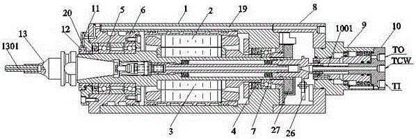
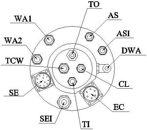
[0029] see Figure 1-Figure 4 , a high-speed automatic tool-changing electric spindle adopting a non-contact rotary joint of the present invention, the main structure includes: a body 1, a stator 2, a rotor shaft 3, a spring preload mechanism 4, a front bearing 5 and The rear bearing 7, wherein the front bearing 5 and the rear bearing 7 are respectively arranged at both ends of the rotor shaft 3 and the front bearing 5 is installed on a front bearing seat 6. The stator 2 and the rotor shaft 3 are integrated inside the machine body 1. The high-frequency three-phase power output by the external drive mechanism is supplied to the motor through the built-in motor lead EC to drive the main shaft to run at high speed. The maximum speed that can run depends on the front bearing 5 and the rear bearing. The maximum rotational speed of the shaft s...


PUM


Abstract

The invention discloses an automatic high-speed tool replacing electric spindle with a non-contact rotating joint used. The automatic high-speed tool replacing electric spindle comprises a machine body, and a stator, a rotor shaft, a spring pre-tensioning mechanism, a front bearing and a rear bearing are arranged in the machine body. The automatic high-speed tool replacing electric spindle further comprises a connecting base fixed to one end of the machine body, an oil cylinder assembly in rotating connection with the connecting base, a rear end cover arranged at the end of the oil cylinder assembly and a front end cover connected to the other end of the machine body. A tool group with a central water outlet is arranged at the front end of the rotor shaft. The automatic high-speed tool replacing electric spindle abandons a complicated contact sealing structure, conducts non-contact sealing by using compressed air, can obtain higher spindle rotating speed, and meanwhile obtains a better sealing effect by adopting labyrinth seal. The spindle is simple and compact in structure and powerful in function, integrates various functions such as center water outgoing, automatic tool replacing, spindle cooling and motor cooling while rotating at high speed, can be widely applied to high-speed machining of various materials, and is particularly suitable for machining of parts such as cavities with deep holes.

Description

technical field [0001] The invention relates to an electric spindle, in particular to a high-speed automatic tool-changing electric spindle adopting a non-contact rotary joint, which belongs to the field of electromechanical engineering. Background technique [0002] The high-speed electric spindle is a mechatronic power component that integrates the spindle motor to achieve high-speed, high-precision and high-efficiency functions. It is mainly used in high-speed processing machine tools to realize high-speed processing of different materials and improve processing efficiency. [0003] At present, the high-speed electric spindle with automatic tool change with center water outlet function is relatively rare in the market. The main reason is that the traditional rotary joints used for center water outlet are generally contact-type seals, low speed, short life, expensive and insufficient reliability. And the large size is not conducive to the multi-functional integration of th...

Claims


Application Information

Patent Timeline
Patent Type & Authority Patents(China)
IPC IPC(8): B23B19/02B23Q3/157
CPCB23Q1/70B23Q3/157
Inventor 朱旭斌
Owner 江苏华雕机械有限公司
Learn More