Aero-assisted missile fin or wing deployment system

a technology of aero-assisted missiles and deployment systems, which is applied in the field of missile fins or wing deployment systems, can solve the problems of manufacturing complications, deficiency of tests, and increased costs

Active Publication Date: 2022-07-28
RAYTHEON CO
View PDF6 Cites 0 Cited by
  • Summary
  • Abstract
  • Description
  • Claims
  • Application Information

AI Technical Summary

Benefits of technology

[0007]Using the panel as a secondary aerodynamic control surface is advantageous in that only a limited opening force is used to expose the panel to the fluid flow and consequently generate the angular acceleration of the wing. The angular acceleration of the wing ensures that the wing reaches a fully deployed position. Accordingly, in contrast to conventional wing deployment systems, the wing may be deployed without complex and bulky devices. Still another advantage of the panel is that high angular acceleration is caused rapidly during the initial range of motion of the wing. This enables the wing including the wing deployment system to deploy in a short timescale, such as between 10 and 50 milliseconds, which may be desirable for particular applications.

Problems solved by technology

However, the prior attempts are deficient in that they may require additional costs, manufacturing complications, undesirable added mass or bulk, and flight control disturbances in the projectile assembly.

Method used


Image

  • Aero-assisted missile fin or wing deployment system
  • Aero-assisted missile fin or wing deployment system
  • Aero-assisted missile fin or wing deployment system

Examples


Embodiment Construction

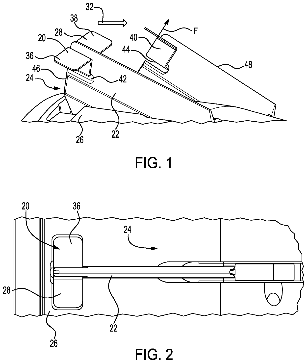
[0053]The principles described herein have particular application in munitions and munition deployment systems, such as in tube-launched or gun-launched projectiles. The projectile and method of deploying the projectile described herein may be suitable for use in military applications. Non-lethal applications and non-military applications may also be suitable, such as surveillance systems. The projectile is suitable for deployment in any environment and may be carried on any suitable platform. Exemplary environments include air, space, and sea, and exemplary platforms include aircraft, hypersonic or supersonic vehicles, land vehicles, or watercraft.

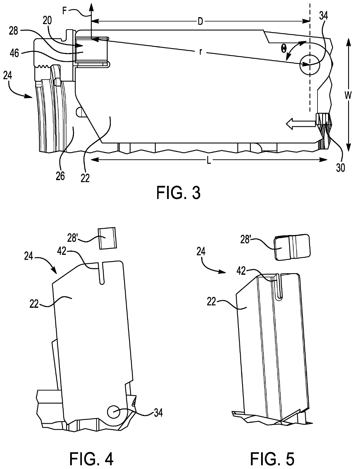
[0054]Referring first to FIGS. 1-3, an exemplary embodiment of a wing deployment system 20 for deploying a fin or wing 22 of a projectile 24 is shown. The projectile 24 described herein may be launched or deployed from a gun or tube. The projectile 24 may be fired by initiating a primer which causes a propellant in the gun to burn thereby...


PUM


Abstract

A projectile and method of deploying a projectile includes a wing deployment system for deploying a wing of a projectile. The wing deployment system includes a stored energy release mechanism that is activated to generate an initial range of motion of the wing and a panel arranged on the wing and configured to cause an angular acceleration of the wing during the initial range of motion of the wing.

Description

GOVERNMENT LICENSE RIGHTS[0001]This invention was made with Government support under contract number DOTC-17-01-INIT0987, awarded by the Department of Defense. The Government has certain rights in the invention.FIELD OF THE DISCLOSURE[0002]The disclosure relates to munitions, and more particularly, to a missile fin or wing deployment system.DESCRIPTION OF THE RELATED ART[0003]Projectiles that are launched by guns or tubes may be suitable for different applications. For example, military applications that use munitions may be a suitable application. The projectiles include fins or wings to increase the stability of the projectile during and after deployment of the projectile from the gun or tube. Prior attempts to deploy the fins or wings include using explosive gas generators, springs or other stored energy mechanisms. However, the prior attempts are deficient in that they may require additional costs, manufacturing complications, undesirable added mass or bulk, and flight control d...

Claims


Application Information

Patent Timeline
Patent Type & Authority Applications(United States)
IPC IPC(8): F42B10/14
CPCF42B10/14
Inventor BUGGE, JOHN F.EDGAR, BYRON T.
Owner RAYTHEON CO
Why Eureka
Try Eureka