
Motor-driven machine tool

一种马达驱动、工具机的技术,应用在制造工具、机动的其他往复式锯床、金属加工设备等方向,能够解决工具机舒适性损失等问题,达到减小振动、减小震动负荷的效果

Active Publication Date: 2010-03-03
ROBERT BOSCH GMBH
View PDF1 Cites 22 Cited by
  • Summary
  • Abstract
  • Description
  • Claims
  • Application Information

AI Technical Summary

Problems solved by technology

[0003] Basically, in such a grinding device with an eccentric drive, unbalanced vibrations occur which lead to a loss of comfort when operating the machine tool

Method used


Image

  • Motor-driven machine tool
  • Motor-driven machine tool
  • Motor-driven machine tool

Examples


Embodiment Construction

[0021] The same reference numerals are assigned to the same components in the drawings.

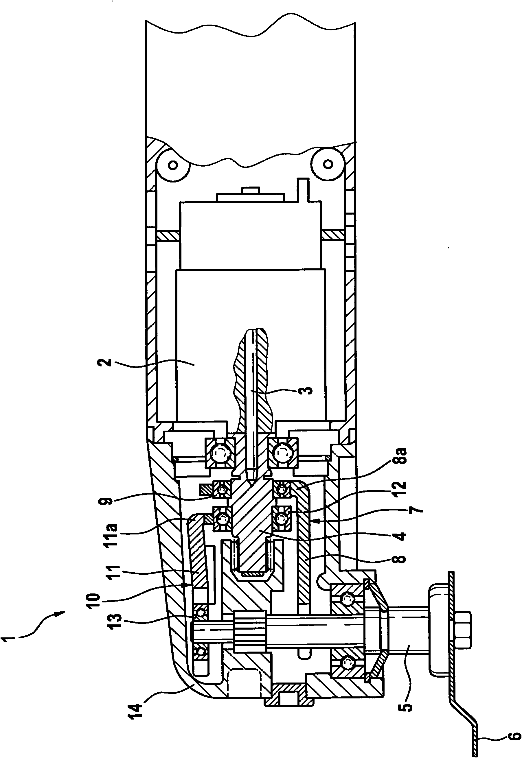
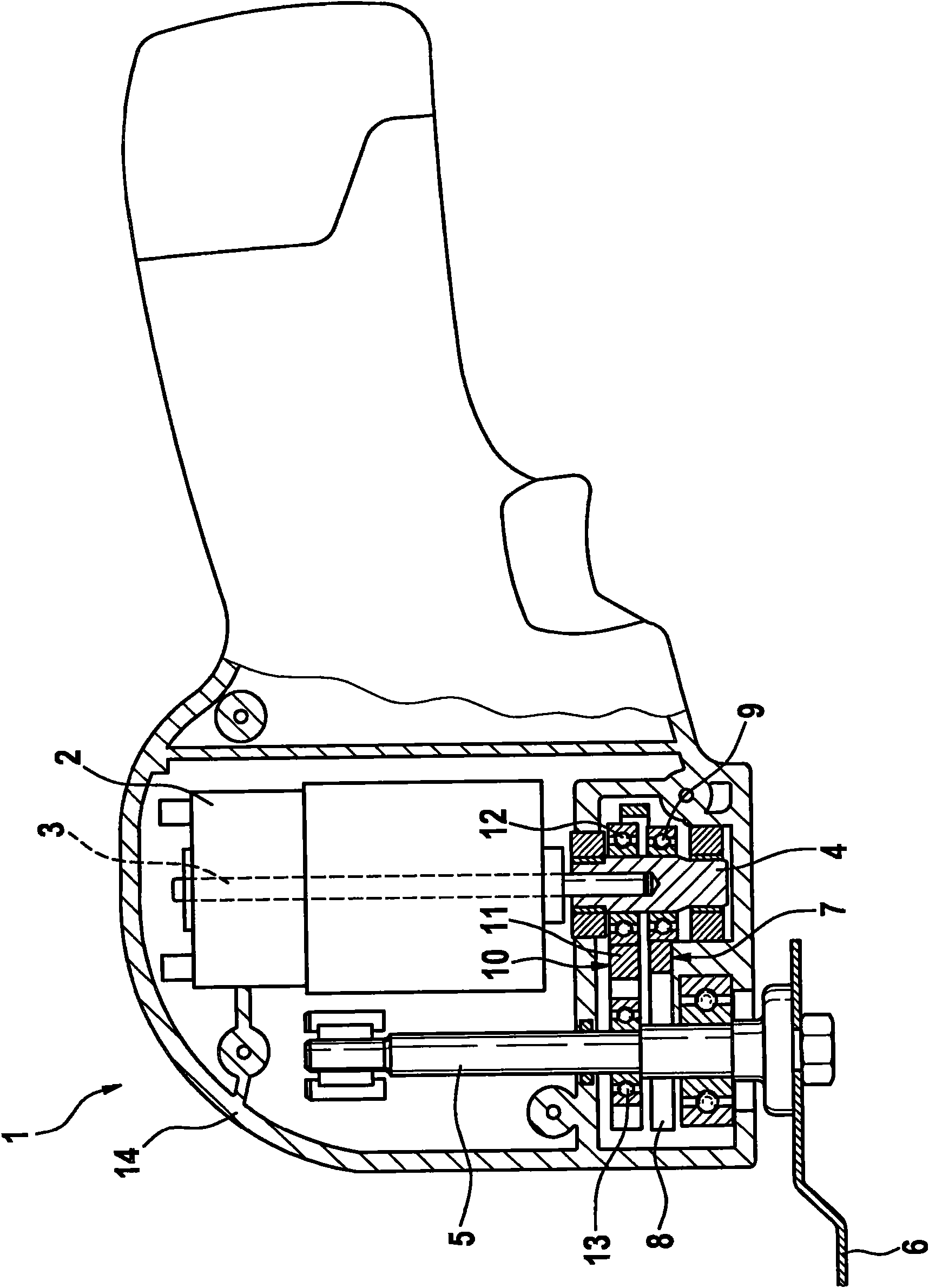
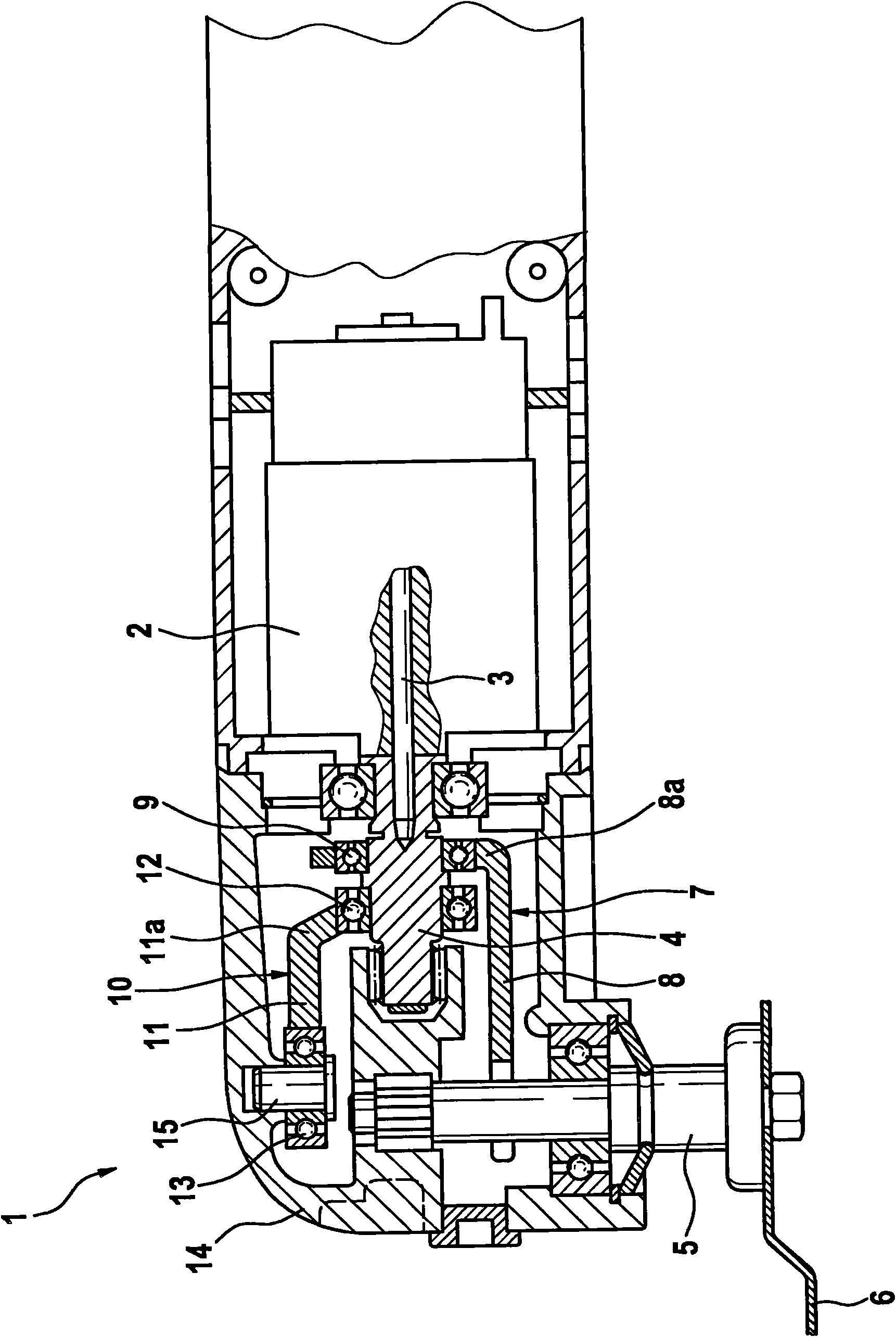
[0022] figure 1 The hand-held power tool 1 shown in has an electric drive motor 2, whose armature 3 is fixedly connected to a coaxial drive shaft 4, which drives the driven shaft or working shaft 5 and is mounted on the Tool 6 on driven shaft. When the electric drive motor 2 is actuated, the rotational movement of the drive shaft 4 is converted via an eccentric coupling 7 into a rotational pivoting movement of the output shaft 5 and the tool 6 , usually with an angular offset of a few degrees. The possibility thus exists for the tool 6 to be used both for grinding and for cutting or sawing a workpiece.

[0023] The eccentric coupling device 7 comprises a coupling part which is fixedly connected to the driven shaft 5 and an eccentric part which is fixedly connected to the drive shaft 4, which is designed in this embodiment as a coupling fork 8 and which is designed as an eccentric cam 9...


PUM


Abstract

A motor-driven machine tool with a drive shaft and a driven shaft on which the tool is received comprises an eccentric coupling device via which the rotational movement of the drive shaft is transmissible onto the driven shaft. A mass balancer shaft is provided for compensating vibrations. Said mass balancer shaft is operatively connected to at least one of the shafts and carries out a compensating movement counter to the eccentric coupling movement.

Description

technical field [0001] The invention relates to a motor-driven machine tool according to the preamble of claim 1 , which has a drive shaft driven by a drive unit and a driven shaft on which a tool is received. Background technique [0002] DE 10104993 A1 describes a hand-held power tool for grinding or polishing, the electric drive motor of which acts on the grinding disc via a transmission. Included in the transmission is a switching device, by means of which at least two types of movement of the grinding disc can be selected. On the one hand, vibratory grinding work should be realized, and on the other hand, the grinding disc can only perform a rotational movement to polish the workpiece. For oscillating grinding work, an eccentric drive is provided, by means of which the rotational movement of the drive shaft is converted into an eccentric movement of the grinding disc. [0003] Basically, in such a grinding device with an eccentric drive, unbalanced vibrations occur wh...

Claims


Application Information

Patent Timeline
Patent Type & Authority Applications(China)
IPC IPC(8): B24B23/03B24B41/04
CPCB24B27/08B24B41/042B27B19/006B24B23/04
Inventor A·扎塞尔
Owner ROBERT BOSCH GMBH
Learn More