Rotation angle detection sensor

Pending Publication Date: 2022-08-11
NIPPON ALEPH
View PDF0 Cites 0 Cited by
  • Summary
  • Abstract
  • Description
  • Claims
  • Application Information

AI Technical Summary

Benefits of technology

[0017]The present invention provides a compact, simple-structure, and highly functional r

Problems solved by technology

However, to detect opening or closing of a cover of an automatic warm water washing toilet seat, for example, it

Method used


Image

  • Rotation angle detection sensor
  • Rotation angle detection sensor
  • Rotation angle detection sensor

Examples


Example

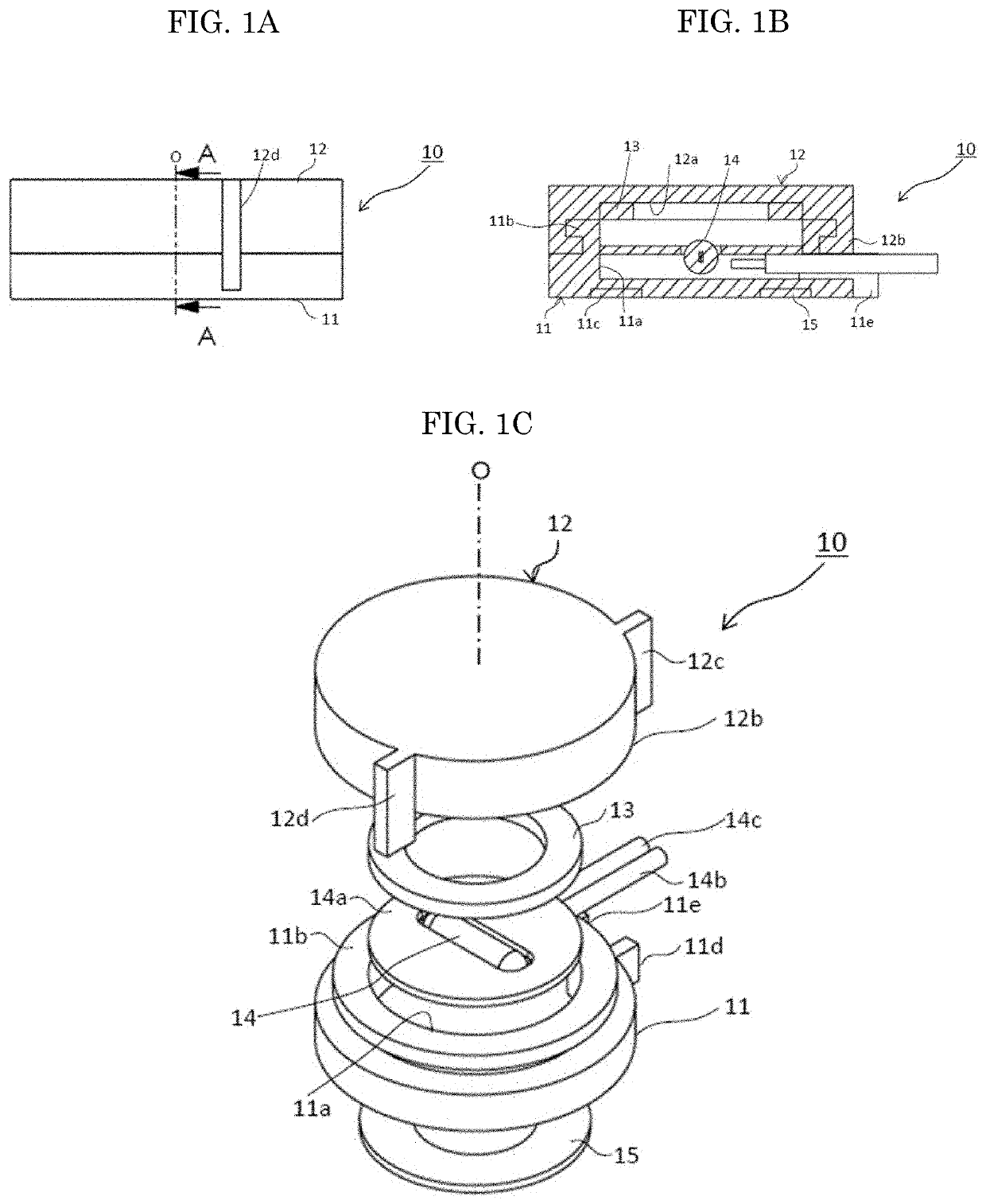
[0039]A first embodiment shown in FIGS. 1A to 5C will hereinafter be described in detail.

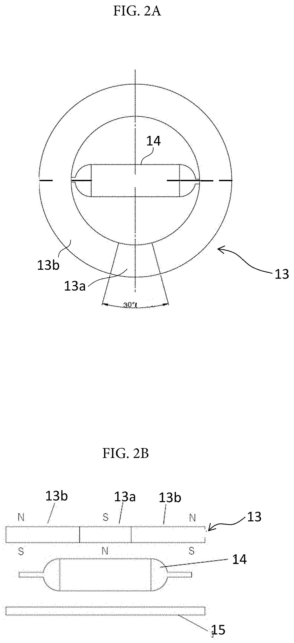
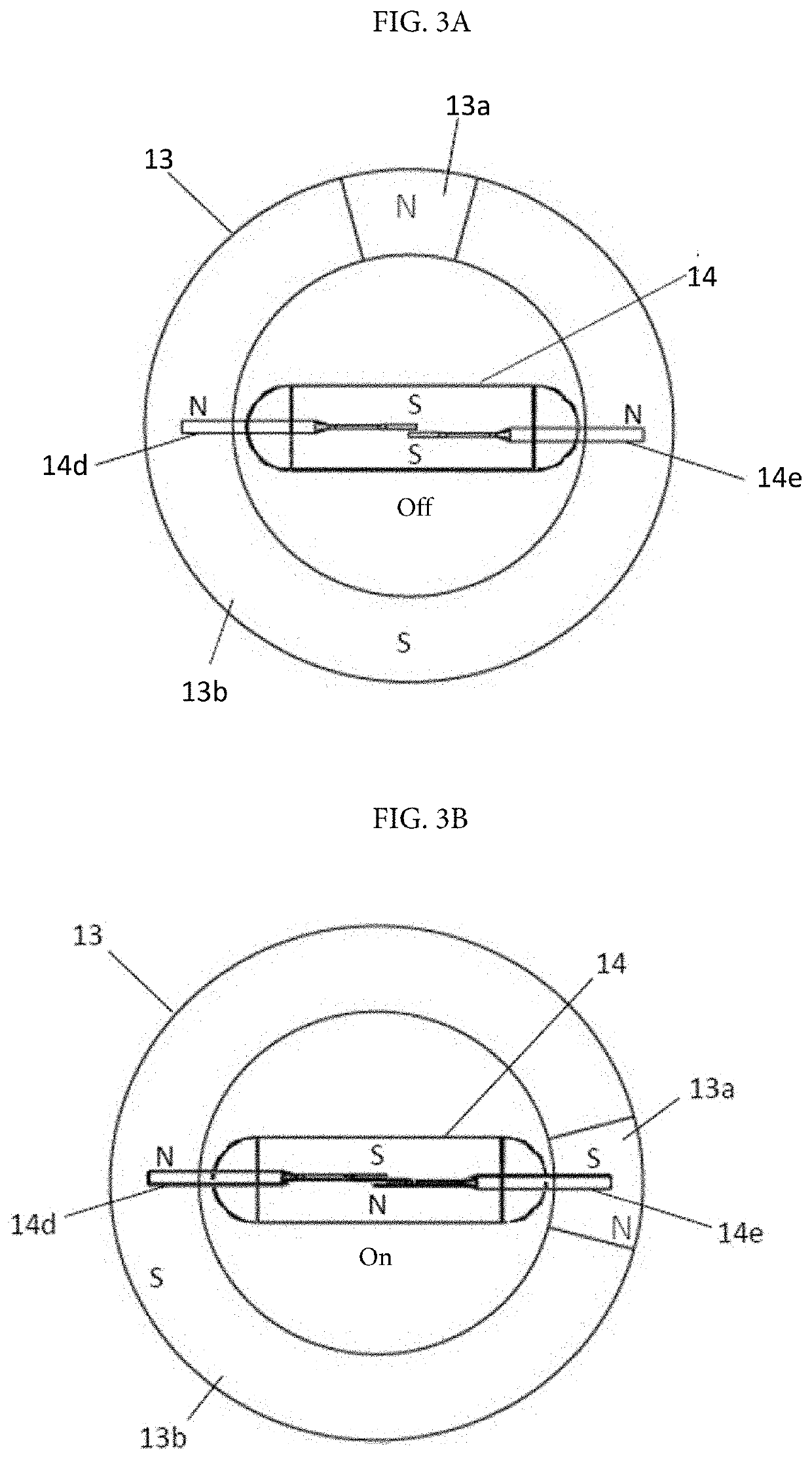
[0040]As shown in FIGS. 1A to 1C, this rotation angle detection sensor 10 includes a base 11, a cover 12, a magnet 13, a reed switch 14, and a back yoke 15. As shown in FIG. 11, the rotation angle detection sensor 10 is mounted to a structure 20 whose rotation angle is to be detected. With the rotation angle detection sensor 10 as shown in FIG. 11, the base 11 is fastened to a fixed part 21 of the structure 20, and the cover 12 is fastened to a rotary shaft 23, for example, of a rotating part 22. The reed switch 14 is accepted by the base 11, and the magnet 13 is housed in the cover 12. Reverse mounting is also allowed: the base 11 may be fastened to the rotary shaft 23 and the cover may be fastened to the fixed part 21 respectively.

[0041]The base 11 of the rotation angle detection sensor 10 is made of a non-magnetic material such as a resin, for example, formed in an approximately flat disk sha...

Example

[0066]With the rotation angle detection sensor 30 in embodiment 2, when the area 13a of the magnet 13 is positioned perpendicular to the longitudinal direction of the reed switch 14 as shown in FIG. 3A, the same poles of the magnet 13 are lined up in the longitudinal direction of the reed switch 14, turning off the reed switch 14, which occurs twice during one turn. From this state, the rotating part 22 of the structure 20 rotates, allowing the cover 12 to be rotated around the rotary shaft 23 and the area 13a of the magnet 13 to be positioned in the longitudinal direction of the reed switch 14 as shown in FIG. 3B, and the opposite poles of the magnet 13 are line up in the longitudinal direction of the reed switch 14, turning on the reed switch 14. The rotation angle detection sensor 30 can thus detect that the rotation angle of the rotating part 22 is within a specified angle range with respect to the fixed part 21 of the structure 20.

[0067]The inventor et. al made a prototype of t...


PUM


Abstract

A rotation angle detection sensor detects the rotation angle of a rotating part attached to a structure including a fixed part and a rotating part that rotates around a rotary shaft. The rotation angle detection sensor includes a reed switch attached to the fixed or rotating part with reeds placed near the rotary shaft. An annular magnet is attached to the rotating or fixed part. A magnetic circuit is formed with respect to the reed switch, with its central axis arranged concentrically with the rotary shaft. When the magnet rotates around the central axis with respect to the reed switch, if the same poles of the magnet are lined up in the longitudinal direction of the reed switch, the reed switch is turned off. If opposite poles of the magnet are lined up in the longitudinal direction of the reed switch, the reed switch is turned on.

Description

TECHNICAL FIELD[0001]The present invention relates to a rotation angle detection sensor for detecting opening and closing of a rotating part such as a cover attached rotatably around a rotary shaft of a structure, for example.BACKGROUND ART[0002]To detect the rotation angle of a rotating part, semiconductor linear sensors including the one using a Hall element or magneto-resistive sensor, non-contact-type position sensor using an IC, or rotary encoder and resistive position sensor are known in the prior art. These sensors can detect rotation angles with high accuracy although they require the driving power supplies.[0003]However, to detect opening or closing of a cover of an automatic warm water washing toilet seat, for example, it is unnecessary to ensure detection accuracy as high as that of a highly expensive rotation angle detection sensor. That is why rotation detection sensors and rotation angle detection sensors that use inexpensive reed switches are also known.[0004]Patent L...

Claims


Application Information

Patent Timeline
IPC IPC(8): H01H36/00G01D5/251G01B7/30
CPCH01H36/0006G01B7/30G01D5/2515G01D5/245H01H36/0013H01H36/0046H01H3/162
Inventor YAJIMA, KOICHIKOSUGE, EIICHIHAGIYAMA, MASAYA
Owner NIPPON ALEPH
Why Eureka
Try Eureka