Liquid supply system

a liquid supply system and liquid technology, applied in the field of liquid supply systems, can solve the problems of system unhygienic, liquid wastage, general unknown time to depletion,

Pending Publication Date: 2022-08-18
DEB IP
View PDF16 Cites 0 Cited by
  • Summary
  • Abstract
  • Description
  • Claims
  • Application Information

AI Technical Summary

Problems solved by technology

Such systems can be unhygienic due to the open nature of the reservoir.
A significant drawback of such a cartridge-based system is therefore liquid wastage arising from refilling prior to the currently installed cartridge becoming fully depleted.
Time to depletion is generally unknown and unpredictable.
Refilling at the point of depletion may not be convenient, particularly as the liquid dispenser is then rendered temporarily, and depending on the application potentially unacceptably, unusable pending replacement of the cartridge.
But replacing a cartridge prior to depletion of that cartridge undesirably results in liquid wastage.
This not only leads to increased costs, but unnecessary disposal or wastage which is out of keeping with the desire to promote reduced impact to the environment, otherwise known as being environmentally friendly.
A drawback of this system is that is requires replacement of a relatively large reservoir of liquid.
Transporting such large volumes of liquid can be is costly and has environmental impacts.
It can also be time consuming and cumbersome for wash room operatives.
In any of the above systems, refilling or replacing the reservoir or replacing the cartridge in a counter mounted dispensing system is often ergonomically challenging as access to the reservoir or cartridge below the counter is often restricted.

Method used


Image

  • Liquid supply system
  • Liquid supply system
  • Liquid supply system

Examples


third embodiment

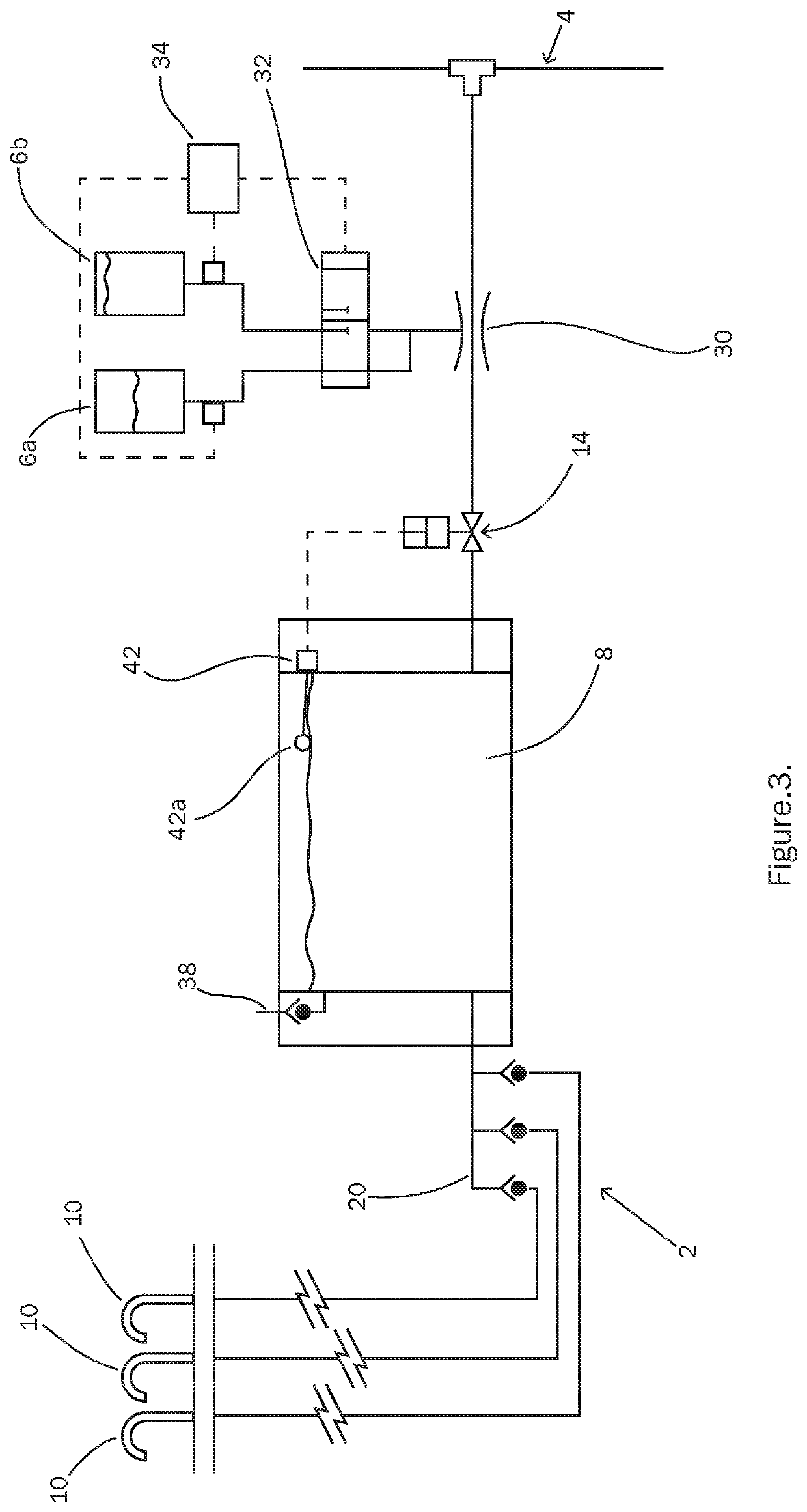
[0131]FIG. 3 illustrates the disclosure. Like features are indicated with the same reference numerals. Only those features which are different from the previous embodiments will be described for the sake of brevity.

[0132]In the embodiment illustrated in FIG. 3, the soap reservoir 8 includes a float valve 42 having a float 42a, which floats on the surface of the soap in the soap reservoir 8.

[0133]The float valve 42 is configured to detect when the amount of soap in the soap reservoir 8 is at a predetermined maximum amount, corresponding to a predetermined position of the float 42a. When this is the case, the float valve 42 provides feedback to the piston operated solenoid valve 14 to cause the valve 14 to shut. This prevents further filling of the soap reservoir 8 and so prevents overfilling.

[0134]As the level of soap in the soap reservoir 8 decreases level of the float 42a also drops. The system is configured such that when the float 42a of the float valve 42 drops by a predetermine...

fourth embodiment

[0135]FIG. 4 illustrates this disclosure. Like features are indicated by the same reference numerals. Only those features which differ from those of the previous embodiments will be described for the sake of brevity.

[0136]In this embodiment, the reservoir has three outlets 18, one for each of the soap dispensers 10. In addition, the soap reservoir 8 is a collapsible reservoir which is arranged to collapse as soap is dispensed from the reservoir. As the soap reservoir 8 is depleted, a change in pressure can be detected in the supply line 28. A pressure switch 44 is provided in the supply line 28 and is arranged to detect changes in pressure corresponding to a fill condition of the soap reservoir 8. When the soap reservoir 8 is empty or drops below a predetermined minimum amount, a corresponding pressure will be detectable in the supply line 28. This pressure is detected by the pressure switch 44 which communicates with a pump 46 to pump water through the supply line 28. This causes t...

fifth embodiment

[0141]FIG. 5 illustrates the disclosure. Like features are indicated by the same reference numerals. Only those features which differ from those of the previous embodiments will be described for the sake of brevity.

[0142]A header tank 50 is provided between the soap reservoir 8 and the dispensers 10. The header tank 50 has an inlet 52 and an outlet 54. The inlet 52 is coupled to the outlet 18 of the liquid reservoir 8 via a supply line 56. The outlet 54 of the header tank 50 is coupled to the series of dispensers 10 via manifold 20 and supply lines 22, 24.

[0143]The header tank 50 has a smaller volume than the soap reservoir 8 and is configured to be supplied with liquid from the liquid reservoir 8. The header tank 50 is configured to supply liquid to the or each dispenser 10 when required. For example, this may be advantageous when the soap reservoir 8 is being replenished, and / or when replenishment of the soap reservoir 8 has been halted (e.g. awaiting refill or replacement of the ...


PUM


Abstract

A liquid supply system for supplying liquid to one or more liquid dispensers is provided. The system comprises a water source for supply of water to the system; a concentrate reservoir for supply of concentrate to the system; and a liquid reservoir coupled to the water source and the concentrate reservoir, and configured to be coupled to one or more liquid dispensers. In use, the liquid reservoir is configured to supply liquid to the or each dispenser and is replenished via the water source and concentrate reservoir.

Description

FIELD OF THE INVENTION[0001]The present disclosure relates to a liquid supply system for supplying liquid to one or more liquid dispensers.BACKGROUND OF THE INVENTION[0002]Liquid dispensers, e.g. soap dispensers, are often provided in washrooms, kitchens and other public facilities. Dispensers can be wall mounted or counter mounted and typically are supplied with liquid e.g. soap from a reservoir.[0003]As the dispensers are used the amount of soap in the reservoir is depleted and so needs to be replenished. In some systems, the reservoir is open and can be refilled by pouring in additional soap from a separate vessel. Such systems can be unhygienic due to the open nature of the reservoir.[0004]In other systems, the reservoir is a collapsible cartridge which can be replaced with a new cartridge as and when required. Although these are generally considered to be more hygienic, in practice, the collapsible cartridges are often replaced before being completely empty. A significant drawb...

Claims


Application Information

Patent Timeline
Patent Type & Authority Applications(United States)
IPC IPC(8): A47K5/12
CPCA47K5/1217A47K2005/1218A47K5/1202A47K5/14A47L15/4418E03C1/046
Inventor LIMBERT, DEAN
Owner DEB IP
Why Eureka
Try Eureka