Liquid lens control apparatus
Pending Publication Date: 2022-08-18
LG INNOTEK CO LTD
View PDF0 Cites 0 Cited by
- Summary
- Abstract
- Description
- Claims
- Application Information
AI Technical Summary
Benefits of technology
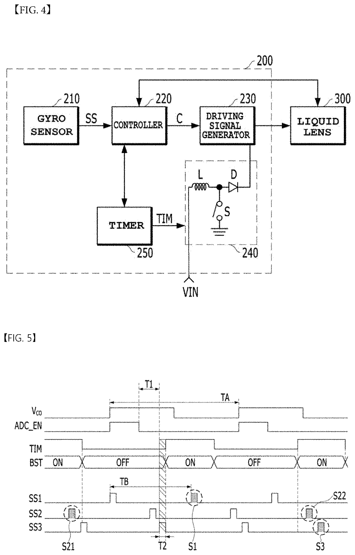
The patent describes a liquid lens control system that improves the function of a camera module using a motion signal. The system eliminates or reduces noise in the signal, which improves the accuracy of the optical image stabilization (OIS) process. This result also improves the suppression ratio of the liquid lens when the excitation frequency is between 2 Hz and 10 Hz.
Problems solved by technology
However, the lens-moving apparatus consumes a lot of power, and an additional cover glass needs to be provided separately from a camera module in order to protect the lens-moving apparatus, thus leading to an increase in the overall size of the conventional camera module.
However, a gyro sensor has a problem of being sensitive to noise.
Method used
View moreImage
Smart ImageViewing Examples

Examples
Embodiment Construction
[0124]Various embodiments have been described in the best mode for carrying out the disclosure.
INDUSTRIAL APPLICABILITY
[0125]A liquid lens control apparatus according to the embodiments may be used in portable devices such as, for example, camera / video devices, telescopic devices, microscopic devices, an interferometer, a photometer, a polarimeter, a spectrometer, a reflectometer, an auto-collimator, a lens-meter, a smartphone, a laptop computer, and a tablet computer.
Login to view more PUM
 Abstract
According to an embodiment, a liquid lens control apparatus includes a liquid lens configured to control an interface between liquids in response to a driving voltage, a voltage booster configured to increase the level of a supply voltage and output a voltage having a higher level than the supply voltage, a controller configured to control the driving voltage, and a gyro sensor configured to sense the movement of the liquid lens and output a signal corresponding to the movement of the liquid lens. The controller acquires a signal corresponding to the movement of the liquid lens output from the gyro sensor during a period in which the voltage booster is in an OFF state, and controls the driving voltage using the signal corresponding to the movement of the liquid lens.
Description
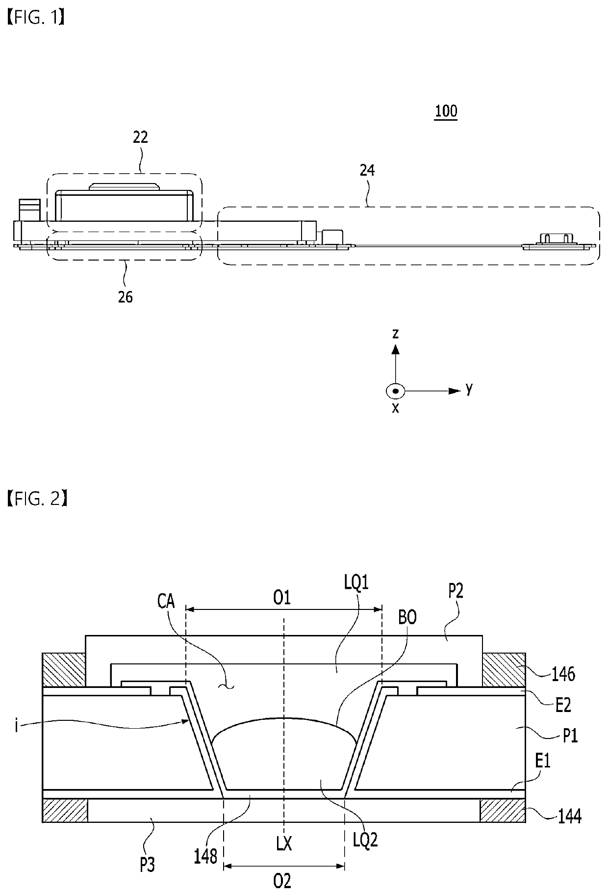
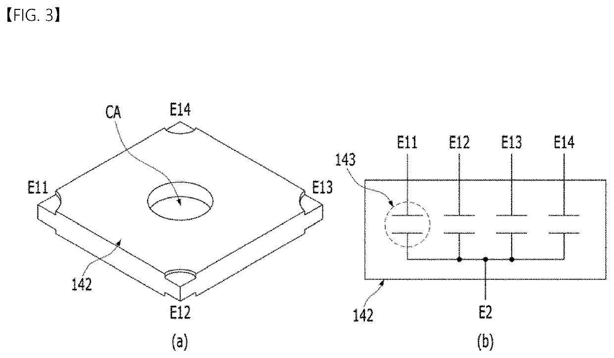
TECHNICAL FIELD[0001]Embodiments relate to a liquid lens control apparatus.BACKGROUND ART[0002]People who use portable devices demand optical devices that have high resolution, are small, and have various photographing functions. For example, the various photographing functions may include at least one of an optical zoom-in / zoom-out function, an auto-focusing (AF) function, or a hand-tremor compensation or optical image stabilization (OIS) function.[0003]Conventionally, the aforementioned various photographing functions are realized by combining a plurality of lenses and directly moving the combined lenses. In the case in which the number of lenses is increased, however, the size of an optical device may increase.[0004]The AF function and the OIS function are performed by moving or tilting a plurality of lenses, which are fixed to a lens holder and are aligned with an optical axis, in the optical-axis direction or in a direction perpendicular to the optical axis. To this end, a sepa...
Claims
Login to view more Application Information
Patent Timeline
 IPC IPC(8): G02F1/29G01C19/00
CPCG02F1/294G01C19/00G02B3/14
Inventor PARK, JUNG BAEKIM, CHANG WOOKPARK, YONG SUNG
Owner LG INNOTEK CO LTD
- R&D Engineer
- R&D Manager
- IP Professional
Why Eureka
- Industry Leading Data Capabilities
- Powerful AI technology
- Patent DNA Extraction
Try Eureka
Browse by: Latest US Patents, China's latest patents, Technical Efficacy Thesaurus, Application Domain, Technology Topic.
© 2024 PatSnap. All rights reserved.Legal|Privacy policy|Modern Slavery Act Transparency Statement|Sitemap