
Vertical Jump Measurement System

a measurement system and vertical jump technology, applied in the direction of gymnastic exercise, rulers for direct reading, sport apparatus, etc., can solve the problems of corrosion of the tubes, preventing the athlete from easily extending and retracting the telescopic tubes, and not being painted

Active Publication Date: 2022-08-25
THE TOP HOPPER LLC
View PDF2 Cites 0 Cited by
  • Summary
  • Abstract
  • Description
  • Claims
  • Application Information

AI Technical Summary

Benefits of technology

The patent describes a vertical jump height measurement system that is lightweight, durable, adjustable, and repeatable. The system is mounted on a mounting surface and includes inner and outer channel members with indicator members that rotate and slide along a vertical axis. The system can be adjusted for ease of use by extending the inner slide assembly or the inner channel member. The method of using the system involves measuring an athletic's vertical jump by recording the top indicator reached by the athlete. The technical effects of the patent are a vertical jump height measurement system that is convenient, accurate, and adaptable for different situations.

Problems solved by technology

Telescopic steel tubes, however, should not be painted because this would impact clamping and wear off during use.
Corrosion of the tubes is a major problem and prevents the athlete from easily extending and retracting the telescopic tubes.
Devices of the prior art suffer here because the mounting structures cannot achieve this because they need telescopic capabilities.
In addition to the functionality of the device, the athlete must be able to easily record their standing reach and their measurement at the peak of their jump from the ground; prior art devices make this task very difficult.
Some prior art device indicators either lack numeric indicia or provide numeric indicia that are not easily read or do not correlate properly with the height the indicator measures from the ground.
While some measurements are etched into the tubes, the etching on the telescopic steel tubes is hard to read and hard to correlate to the position of the indicators.
Prior art devices do not have positive stops integrated into the extension tube design.
All of these issues will lead to errors in recording the athlete's measurements.

Method used


Image

  • Vertical Jump Measurement System
  • Vertical Jump Measurement System
  • Vertical Jump Measurement System

Examples


Embodiment Construction

[0031]The foregoing and other features and advantages of the invention will become more apparent from the following detailed description of exemplary embodiments, read in conjunction with the accompanying drawings. The detailed description and drawings are merely illustrative of the invention rather than limiting, the scope of the invention being defined by the appended claims and equivalents thereof.

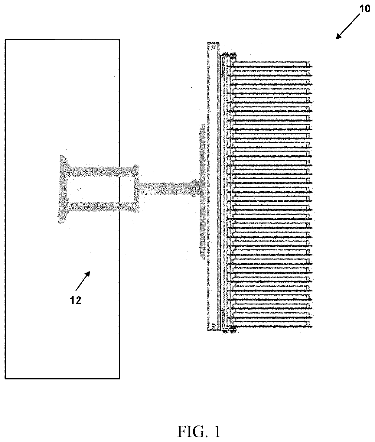
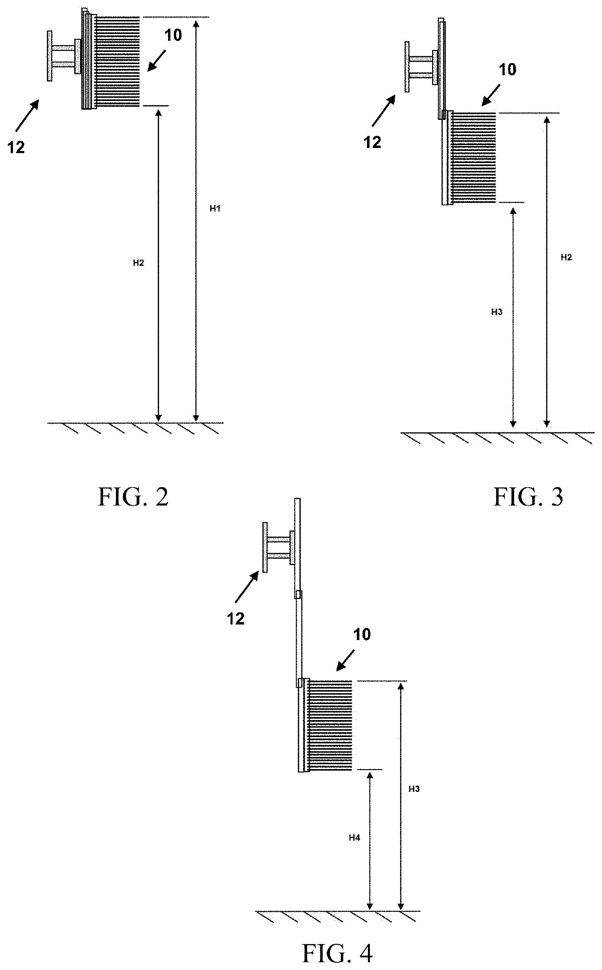
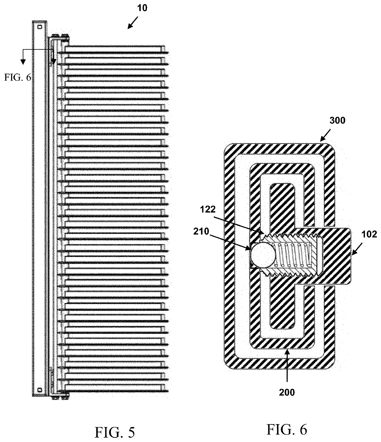
[0032]As shown in FIGS. 1-6, in an exemplary embodiment, the system 10 is mounted to a mounting surface 12. The system 10 comprises an inner slide assembly 100 coupled to an inner channel member 200, the inner channel member 200 further coupled to an outer channel member 300. In this configuration, system 10 is mounted to a mounting surface 12 through the outer channel member 300, the inner channel member 200 is configured in a first state to freely traverse along a vertical axis 302 of the outer channel member 300 and fixed at a single point on the vertical axis 302 in a second state, ...


PUM


Abstract

The invention comprises a plurality of indicator members rotatably coupled to an inner slide assembly, the inner slide assembly coupled to an inner channel member, the inner channel member further coupled to an outer channel member. In this configuration, system is mounted to a mounting surface through the outer channel member, the inner channel member is configured in a first state to freely traverse along a vertical axis of the outer channel member and in configured in a second state fixed at a single point on the vertical axis, and inner slide assembly is configured in a first state to freely traverse along a vertical axis of the inner channel member and in a second state fixed at a single point on the vertical axis.

Description

BACKGROUND OF THE INVENTION[0001]The present invention generally relates to the field of vertical jump measurement. More particularly, the invention relates to a system configured to measure the vertical jump height of an athlete.[0002]The vertical jump is the act of jumping in the air against gravity to raise oneself off of the ground. In athletics, a vertical jump is often referred to as a measure of how high an individual or athlete can elevate off of the ground.[0003]To measure the vertical jump two measurements are required. The first measurement is the standing reach. The athlete will stand with both feet flat on the ground and reaching up with one hand. The height of the standing reach is recorded. The second measurement is the highest reach by the athlete during the peak of the athlete's jump. The athlete will jump up as high as possible and reach one hand up during the peak of the jump striking an indicator. That measurement is recorder. The difference between the standing ...

Claims


Application Information

Patent Timeline
IPC IPC(8): A63B5/16G01B3/08
CPCA63B5/16G01B3/08A63B2225/093A63B2220/13A63B5/02A63B2220/20A63B2071/0694A63B71/0622A63B2244/081A63B71/06
Inventor MERVIS, SCOTT
Owner THE TOP HOPPER LLC
Learn More