
Elevator for Heavy Load Pipe Lifting, Pipe for Such Elevator and Pipe Handler Assembly Comprising Such Elevator

Pending Publication Date: 2022-08-25
NAT OILWELL VARCO NORMAY AS
View PDF0 Cites 0 Cited by
  • Summary
  • Abstract
  • Description
  • Claims
  • Application Information

AI Technical Summary

Benefits of technology

This patent describes an elevator design that has two different shaped surfaces. The first surface is conical, while the second surface can have a lower conicity to reduce stress. This design also reduces stress in the transition region between the two surfaces. Additionally, the patent discusses a thoroïde shape that further reduces stress in both the elevator and the pipe. The technical effects of this design include reduced stress and improved performance of the elevator and pipe.

Problems solved by technology

The inventor of this patent application realized that the interface having an increased angle, such as 45 degrees, reduces the available contact area resulting in excessive bearing stresses between the drill pipe elevator shoulder and the elevator bushing.
Reducing the transition radius R between the axial pipe body and the pipe lifting shoulder (typically 1.5″ (38.1 mm) would help, however it would increase the stress concentration in that transition radius which may adversely affect fatigue life of the pipe.
An increased outside diameter (OD) of the tool joint is another consideration, however most power tongs (including Iron Roughnecks (IRN)) currently used in the field would not be able to handle such a large tool joint OD.

Method used


Image

  • Elevator for Heavy Load Pipe Lifting, Pipe for Such Elevator and Pipe Handler Assembly Comprising Such Elevator
  • Elevator for Heavy Load Pipe Lifting, Pipe for Such Elevator and Pipe Handler Assembly Comprising Such Elevator
  • Elevator for Heavy Load Pipe Lifting, Pipe for Such Elevator and Pipe Handler Assembly Comprising Such Elevator

Examples


Embodiment Construction

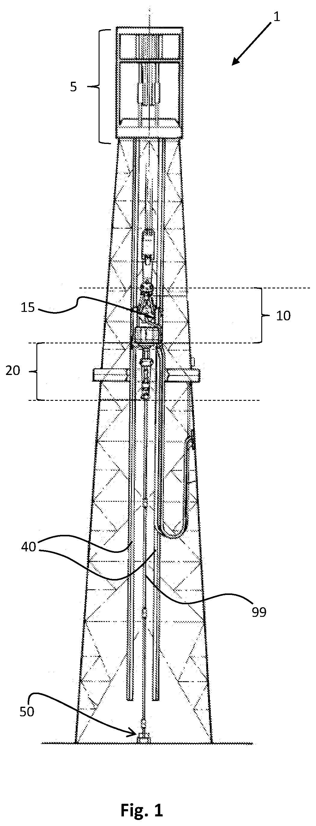
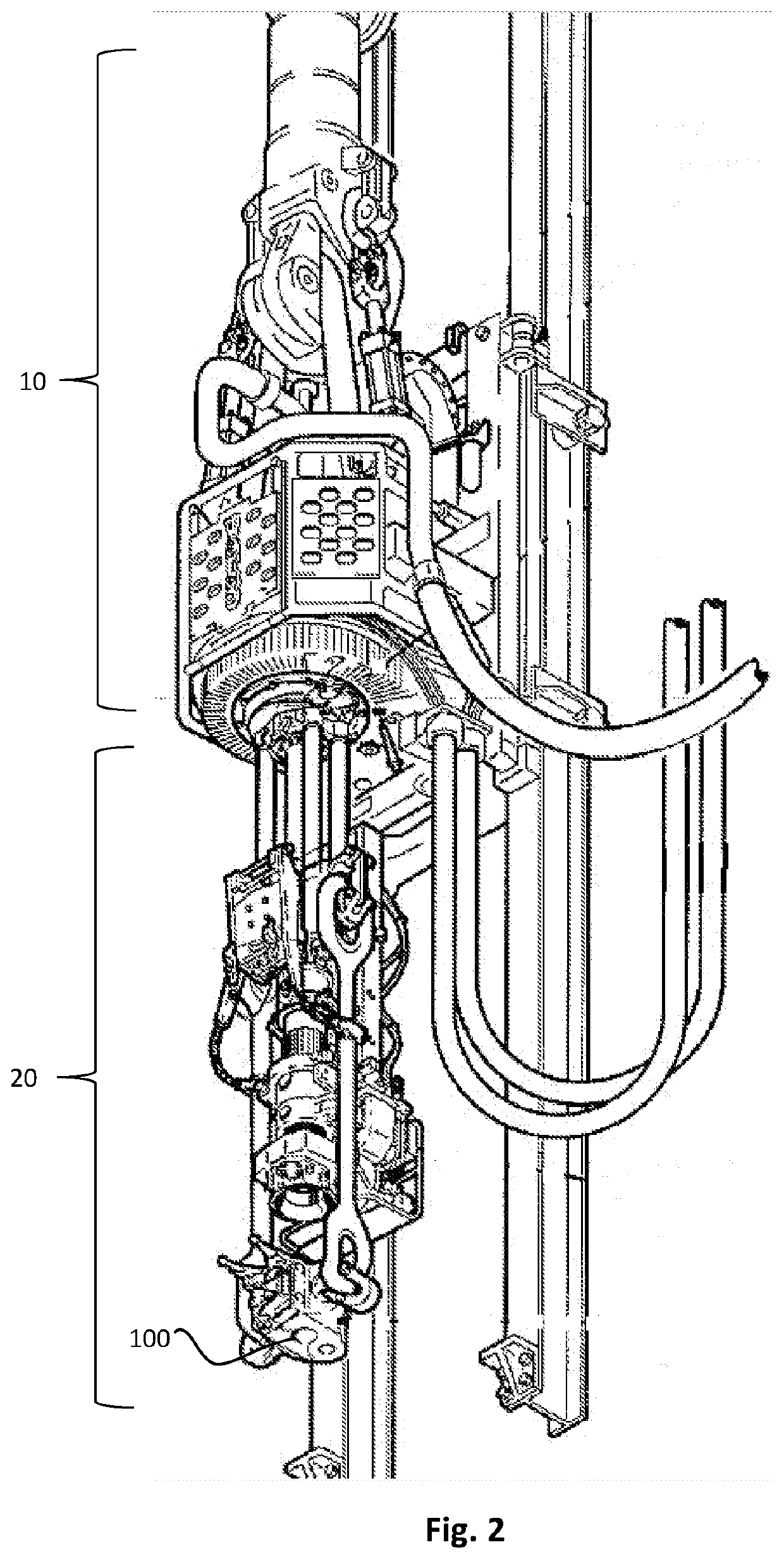
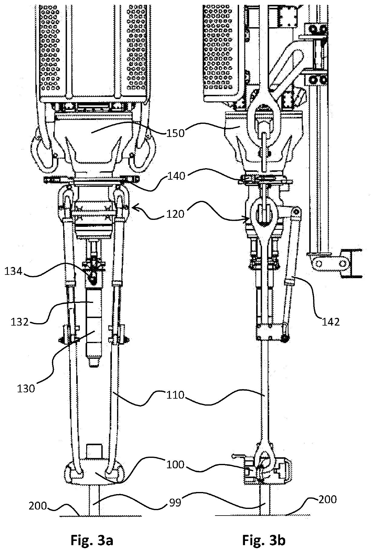
[0041]Various illustrative embodiments of the present subject matter are described below. In the interest of clarity, not all features of an actual implementation are described in this specification. It will of course be appreciated that in the development of any such actual embodiment, numerous implementation-specific decisions must be made to achieve the developers' specific goals, such as compliance with system-related and business-related constraints, which will vary from one implementation to another. Moreover, it will be appreciated that such a development effort might be complex and time-consuming but would nevertheless be a routine undertaking for those of ordinary skill in the art having the benefit of this disclosure.

[0042]The present subject matter will now be described with reference to the attached figures. Various systems, structures and devices are schematically depicted in the figures for purposes of explanation only and to not obscure the present disclosure with det...


PUM


Abstract

Disclosed is an elevator for holding and end portion of a pipe in a drill tower. The elevator includes a hole from which, in operational use, an end portion of the pipe is suspended. The minimum diameter of the end portion of the pipe is selected larger than the minimum diameter of the hole, wherein sidewalls of the hole are shaped with a receiving surface for receiving correspondingly-shaped sidewalls of the end portion of the pipe. Similarly, sidewalls of the end portion of the pipe are shaped with an engagement surface for engagement with correspondingly-shaped sidewalls of the hole. Both the receiving surface and the engagement surface includes a first part and a second part neighbouring the first part, the first part defining a frustoconical shape having a first conicity, and the second part defining a shape having at least partially a second conicity lower than the first conicity.

Description

CROSS REFERENCE TO RELATED APPLICATIONS[0001]This present application claims benefit of European Patent Application No. 21158969.2 filed Feb. 24, 2021 and entitled “Elevator for Heavy Load Pipe Lifting, Pipe for Such Elevator and Pipe Handler Assembly Comprising Such Elevator”, which is incorporated herein by reference in its entirety for all purposes.STATEMENT REGARDING FEDERALLY SPONSORED RESEARCH OR DEVELOPMENT[0002]Not applicable.FIELD OF THE DISCLOSURE[0003]The disclosure relates to an elevator for holding an end portion of a pipe in a drill tower. The disclosure further relates to a pipe configured for use with the elevator. The disclosure also relates to a pipe handler assembly comprising such elevator and pipe BACKGROUND OF THE DISCLOSURE[0004]Drill towers generally comprise a pipe handler assembly for handling drill pipes or other tubular structures. An important part of the pipe handler assembly is the elevator, which basically comprises a passive mechanical part that comp...

Claims


Application Information

Patent Timeline
IPC IPC(8): E21B19/06
CPCE21B19/06E21B19/00E21B17/00
Inventor RIJZINGEN, JOHANNES WILHELMUS HENRICUS VANMURADOV, ANDREI
Owner NAT OILWELL VARCO NORMAY AS
Learn More