
Degassing device for preparing secondary battery

a secondary battery and gassing device technology, which is applied in the manufacture of cell components, final products, jackets/cases materials, etc., can solve the problems of excessive pressure in the pressing process, fatal limitation of the degassing process in the related art, and excessive speed of degassing chamber, etc., to achieve sufficient evacuation time and shorten the degassing process time

Pending Publication Date: 2022-08-25
CLEVER
View PDF0 Cites 0 Cited by
  • Summary
  • Abstract
  • Description
  • Claims
  • Application Information

AI Technical Summary

Benefits of technology

The patent allows for a faster way to remove air from a pouch by simultaneously piercing, sealing, and discharging the air. This process helps to decrease the time needed for degassing and ensures that the gas has enough time to escape from the pouch.

Problems solved by technology

Because the gas, which is removed by the degassing process, contains gas harmful to a human body, the degassing process needs to be performed in a state in which a degassing target pouch is accommodated in a chamber sealed from the outside.
That is, not only the gas but also the electrolyte may be discharged when the piercing is performed in the fully depressurized chamber, a speed of depressurizing the chamber is excessively high, or a pressure in the pressing process is excessively high.
For this reason, the degassing process in the related art has a fatal limitation in increasing a speed of performing the process.
For this reason, there is a limitation in number of pouches to be processed per unit time in the degassing process.
During the process of adjusting the pressure in the chamber to the atmospheric pressure, the gas remains in the chamber without being discharged to the outside of the chamber, which causes a problem in that the harmful gas leaks into the atmosphere when the chamber is opened.

Method used


Image

  • Degassing device for preparing secondary battery
  • Degassing device for preparing secondary battery
  • Degassing device for preparing secondary battery

Examples


Embodiment Construction

[0035]Hereinafter, embodiments of a degassing device for preparing a secondary battery according to the present disclosure will be described in detail with reference to the drawings.

[0036]However, it should be noted that the intrinsic technical spirit of the present disclosure is not limited by the following exemplary embodiment, and the following exemplary embodiment may easily be substituted or altered by those skilled in the art based on the intrinsic technical spirit of the present disclosure.

[0037]In addition, the terms used herein are selected for convenience of description and should be appropriately interpreted as a meaning that conform to the technical spirit of the present disclosure without being limited to a dictionary meaning when recognizing the intrinsic technical spirit of the present disclosure.

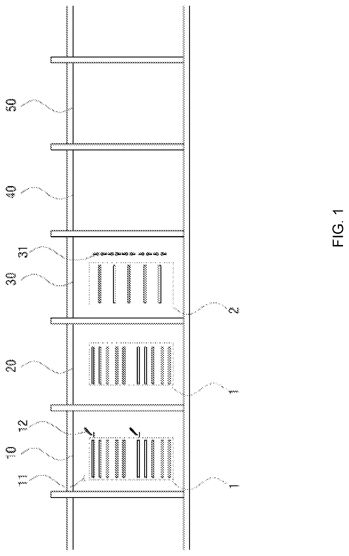
[0038]FIG. 1 is a view illustrating one embodiment of a degassing device for preparing a secondary battery according to the present disclosure.

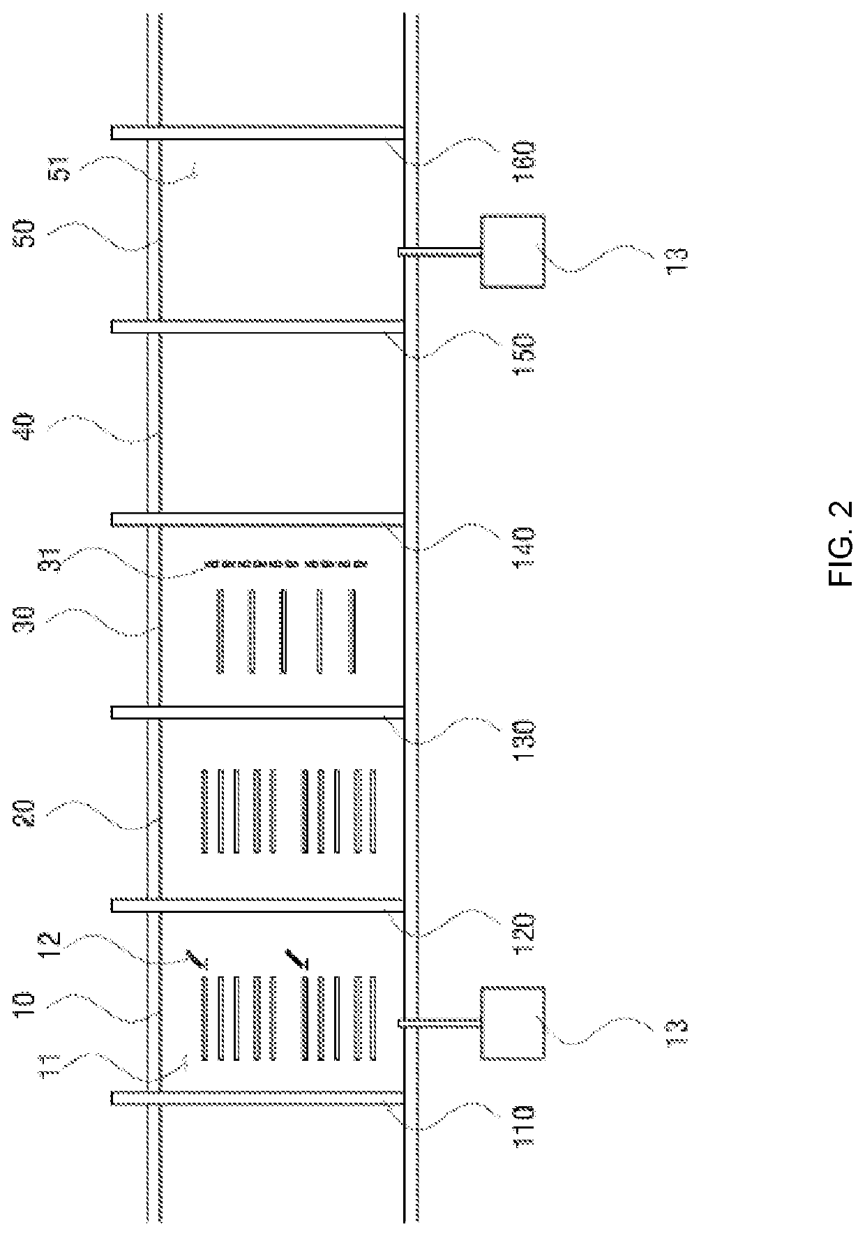
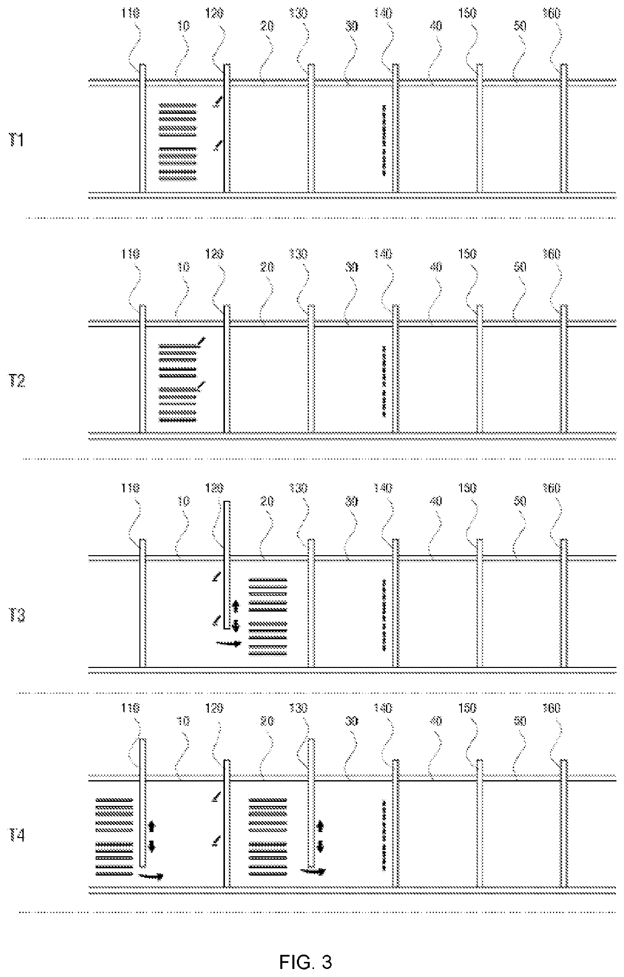
[0039]Referring to FIG. 1, a de...


PUM

PropertyMeasurementUnit
vacuum pressureaaaaaaaaaa
pressureaaaaaaaaaa
vacuum pressureaaaaaaaaaa

Abstract

Disclosed is a degassing device for preparing a secondary battery, the degassing device including a piercing chamber configured to accommodate a first amount of degassing target pouches and having an internal space in which a pressure is selectively controlled to a vacuum pressure or an atmospheric pressure, the piercing chamber including a piercing unit configured to form inner gas discharge paths in the first amount of degassing target pouches, a first buffer chamber having an internal pressure maintained as the vacuum pressure and configured to accommodate the first amount of degassing target pouches unloaded from the piercing chamber, a sealing chamber having an internal pressure maintained as the vacuum pressure and having a sealing unit configured to receive the first amount of degassing target pouches accommodated in the first buffer chamber while sequentially receiving a second amount of degassing target pouches smaller than the first amount of degassing target pouches.

Description

TECHNICAL FIELD[0001]The present disclosure relates to a degassing device for preparing a secondary battery, and more particularly, to a degassing device for preparing a secondary battery, which is capable of increasing a degassing process speed while improving efficiency in removing gas produced in a secondary battery pouch.BACKGROUND ART[0002]This section provides background information related to the present disclosure which is not necessarily prior art.[0003]A process of manufacturing a general pouch-type secondary battery is broadly classified into three processes including an electrode production process, an assembly process, and a charging / discharging process.[0004]The electrode production process manufactures electrode assemblies using positive plates, negative plates, and separators, and the electrode assemblies serve as batteries.[0005]When the assembly process of inputting the manufactured electrode assembly and an electrolyte into a pouch-type encapsulant is completed, a...

Claims


Application Information

Patent Timeline
Patent Type & Authority Applications(United States)
IPC IPC(8): H01M10/04H01M50/342H01M50/367
CPCH01M10/0404H01M10/0481H01M50/3425H01M50/367Y02E60/10Y02P70/50H01M10/058H01M50/317H01M50/116
Inventor JEONG, JONG HONGKIM, SANG JIN
Owner CLEVER
Learn More