Eureka AIR delivers breakthrough ideas for toughest innovation challenges, trusted by R&D personnel around the world.

Actuation apparatus for control of thin wing aircraft surfaces

Pending Publication Date: 2022-09-08
THE BOEING CO
View PDF0 Cites 0 Cited by
  • Summary
  • Abstract
  • Description
  • Claims
  • Application Information

AI Technical Summary

Benefits of technology

The patent describes a new actuation system for high-speed aircraft that reduces drag and improves performance. The system uses thin wings with swept edges that would normally increase drag, but the actuators that control the movement of the wings are aligned with the air stream, reducing most of the drag. The system also has a space-efficient design and is enclosed within a fairing to minimize drag. Overall, the system allows for better control of the wings and reduces the impact of drag on the aircraft's performance.

Problems solved by technology

These features, while reducing aerodynamic drag, increase the difficulty of actuating a moveable surface coupled to the trailing edge of the wing.

Method used


Image

  • Actuation apparatus for control of thin wing aircraft surfaces
  • Actuation apparatus for control of thin wing aircraft surfaces
  • Actuation apparatus for control of thin wing aircraft surfaces

Examples


Embodiment Construction

[0042]Embodiments of the present disclosure are described herein. It is to be understood, however, that the disclosed embodiments are merely examples and other embodiments can take various and alternative forms. The figures are not necessarily to scale; some features could be exaggerated or minimized to show details of particular components. Therefore, specific structural and functional details disclosed herein are not to be interpreted as limiting, but merely as a representative basis for teaching one skilled in the art to variously employ the present disclosure. As those of ordinary skill in the art will understand, various features illustrated and described with reference to any one of the figures can be combined with features illustrated in one or more other figures to produce embodiments that are not explicitly illustrated or described. The combinations of features illustrated provide representative embodiments for typical applications. Various combinations and modifications of...


PUM


Abstract

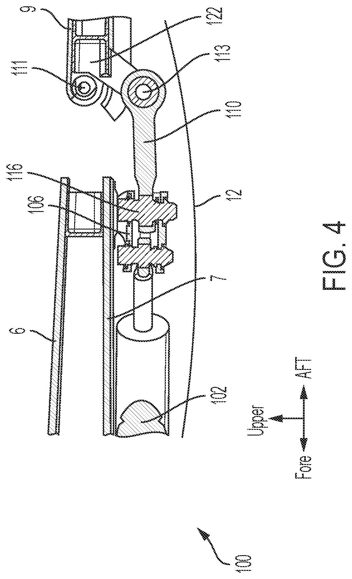
An actuation apparatus for a control surface rotatably coupled to a swept-wing includes a pivot arm coupled to the control surface and proximate the hinged end of the control surface, a drive rod oriented normal to the trailing edge of the swept-wing, the drive rod having an aft end coupled to the pivot arm, a pivot fitting pivotally coupled to a lower surface of the swept-wing by a pivot pin, the pivot fitting having an aft portion coupled to a forward end of the drive rod, and an actuator disposed on the lower surface of the swept-wing. The actuator is coupled to the pivot fitting such that an applied force by the actuator in the streamwise direction rotates the pivot fitting such that the applied force is translated to the drive rod to rotate the control surface.

Description

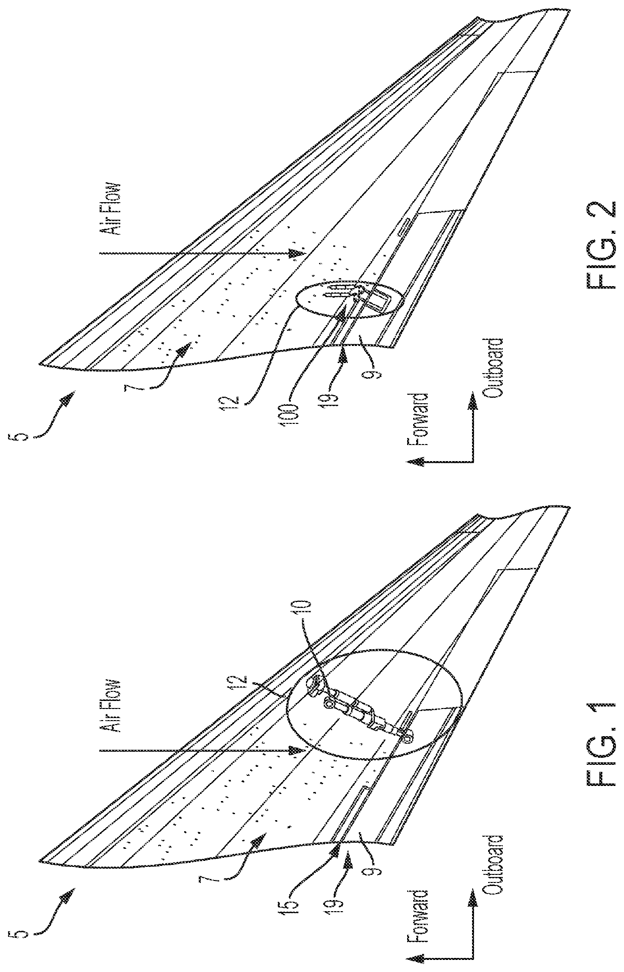
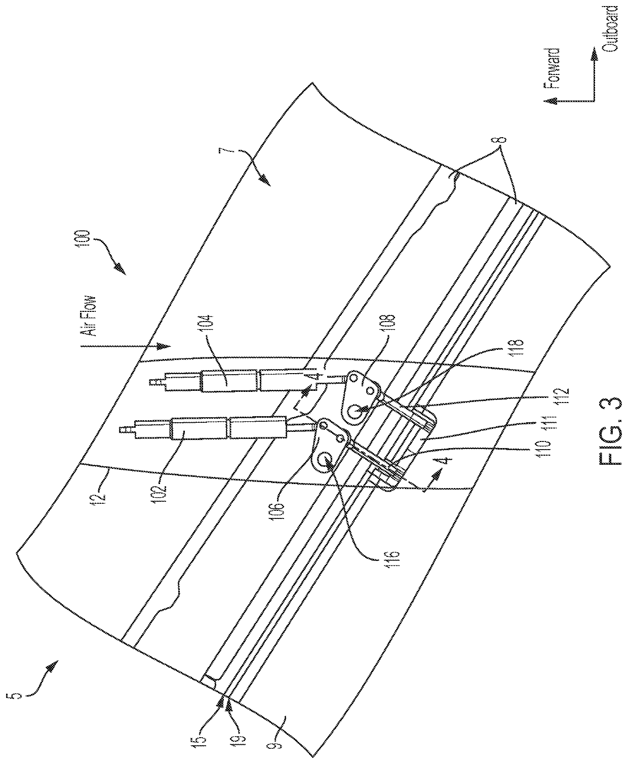
CROSS-REFERENCE TO RELATED APPLICATIONS[0001]This application claims priority to, and the benefit of, U.S. Provisional Patent Application No. 63 / 155,427 filed Mar. 2, 2021, which is hereby incorporated by reference in its entirety.INTRODUCTION[0002]The present disclosure relates to the field of aircraft wing systems and actuation mechanisms and apparatus for controlling a control surface of a thin wing aircraft.[0003]High speed aircraft, such as transonic or hypersonic aircraft, often have thin wings to reduce drag and improve aircraft range and performance. Additional drag benefits can be obtained from sweeping the trailing edge of the wing such that the trailing edge is not normal to the airstream over the wing. These features, while reducing aerodynamic drag, increase the difficulty of actuating a moveable surface coupled to the trailing edge of the wing. Actuators that control a control surface or other moveable surface coupled to the trailing edge of the wing are not aligned wi...

Claims


Application Information

Patent Timeline
IPC IPC(8): B64C13/30B64C9/00B64C30/00B64C3/10
CPCB64C13/30B64C9/00B64C30/00B64C3/10B64C9/02
Inventor YE, MICHAEL YANBOWERS, BRET A.
Owner THE BOEING CO
Why Eureka
Eureka Blog
Learn More