System level device for battery and integrated circuit integration

a battery and integrated circuit technology, applied in the field of system-level power source integration, can solve the problems of large power supply to maintain the quality of service, large cost, and large complexity of current battery management systems

Inactive Publication Date: 2006-08-08
IBM CORP
View PDF28 Cites 16 Cited by
  • Summary
  • Abstract
  • Description
  • Claims
  • Application Information

AI Technical Summary

Benefits of technology

[0021]There are numerous benefits of the integration of chips and a battery, according to the present invention. For example, the present invention greatly reduces the overall system size. Second, the present invention improves the power supply efficiency, since the battery chip is located very close to the system. Hence, the energy waste due to resistive loss caused by having a power supply through a long resistive power bus, is eliminated. Another advantage is that power management becomes easier, since the battery chip includes battery cell arrays in addition to relevant control circuitry. Yet another benefit is the noise due to the power supply is reduced by reducing the wire inductance. Moreover, the present invention allows for decoupling capacitors and regulators to be added, which can also be integrated on the battery chip to manage the noise. Still another advantage of the present invention is that the thermal effect caused by the battery charging and discharging is minimized. Along these lines, by reducing battery heat-up during charging, the battery life span is increased, and the charging efficiency is greatly improved.
is that the thermal effect caused by the battery charging and discharging is minimized. Along these lines, by reducing battery heat-up during charging, the battery life span is increased, and the charging efficiency is greatly improved.

Problems solved by technology

In today's wireless systems and personal systems continuous supply of power to maintain the quality of service becomes a major challenge.
Although there are many new developments in the battery technology for longer usage period, lifetime, and operating environment, the integration of a battery into a system is proving to be bulky and inconvenient.
However, such advanced battery technologies often exhibit characteristics that provide challenges for the designers and manufacturers of advanced energy storage devices.
As such, current battery management systems are vastly complex and cost significantly greater than what can be justified for cheaper devices.
Conventional battery systems, such as those that utilize lead acid for example, are often unsuitable for use in high-power, low-weight applications.
Other known battery technologies may be considered too unstable or hazardous for use in consumer product applications, such as portable wireless devices.
It should be apparent to those skilled in the art that such conventional interconnection approaches provide for little, if any, flexibility when attempting to alter the series and / or parallel hardwired connections between the cells and components.
Moreover, the wiring process typically employed in the fabrication of conventional advanced batteries is generally complicated and time consuming.
These and other design defects typically result in a reduction in the performance and service life of the battery, and often represent a significant safety concern.
Other characteristics of advanced battery technologies provide additional challenges for the designers of advanced energy storage devices.
Such repetitive changes in the physical size of a cell significantly complicates the mechanical housing design and electrical connection strategy.

Method used


Image

  • System level device for battery and integrated circuit integration
  • System level device for battery and integrated circuit integration
  • System level device for battery and integrated circuit integration

Examples


first embodiment

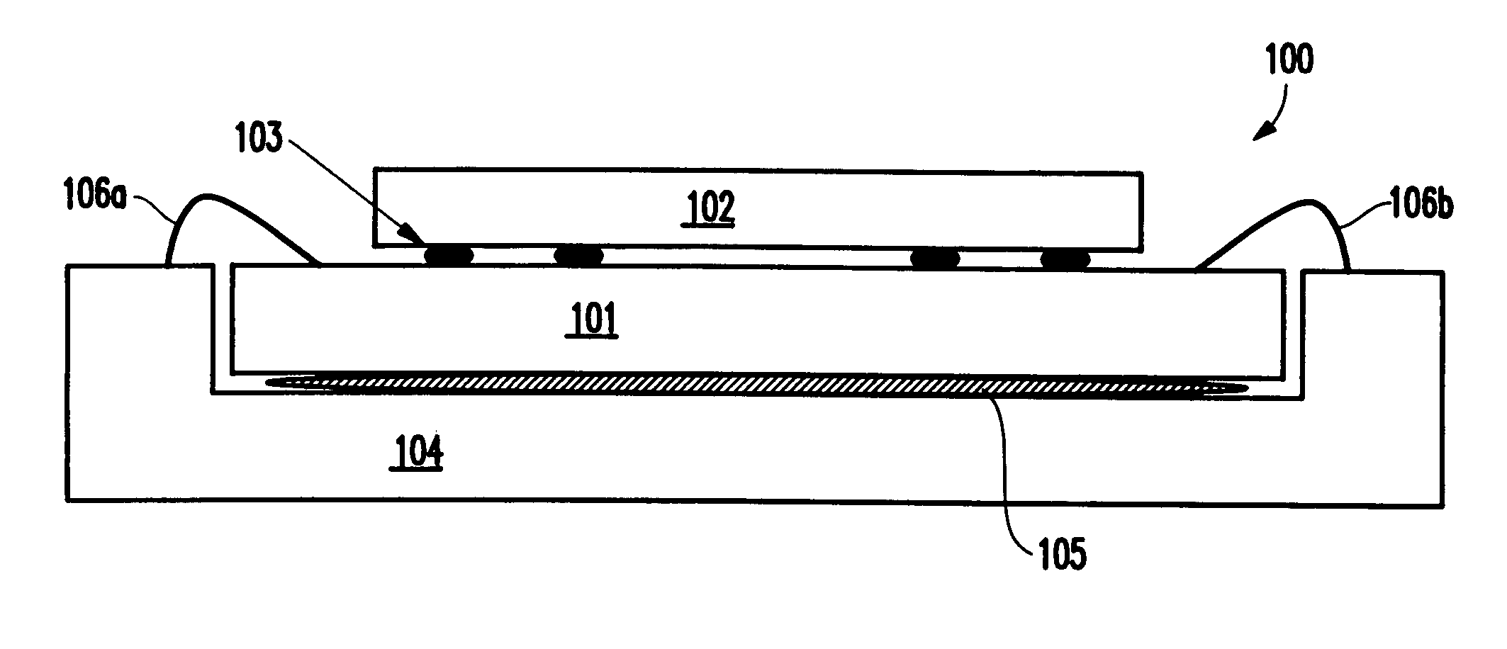
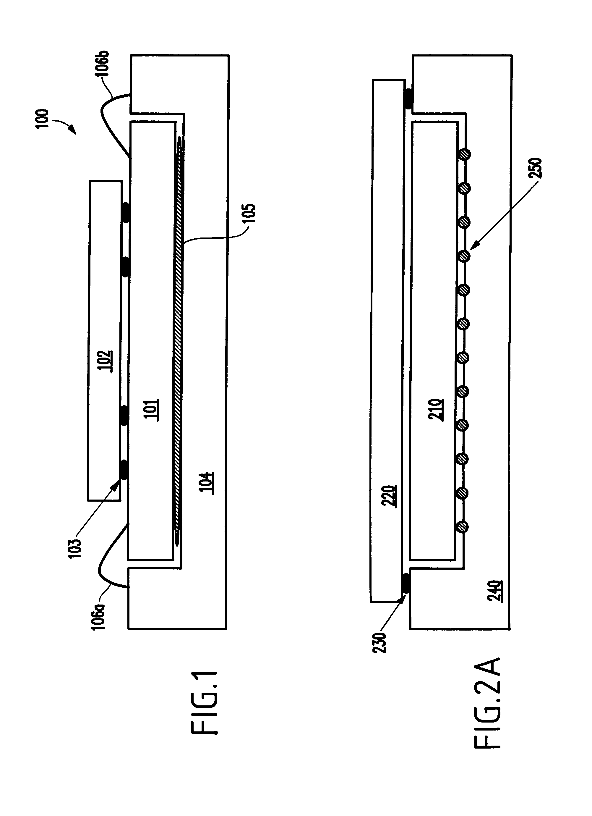
[0030]Referring now to the drawings, and more particularly to FIGS. 1 through 4, there are shown preferred embodiments of the method and structures according to the present invention. In FIG. 1, a schematic diagram of an integrated solid-state battery and chip packaging system 100 is illustrated with a solid-state battery 102 shown on a finished chip 101. The solid-state battery chip (e.g., capacitor, etc.) 102 is soldered to the underside of a chip further comprising an integrated circuit 101. The battery electrodes 103 can be soldered to the chip through a micro-C4 or similar technique to the chip voltage sources. Then the entire stacked chips can be placed into a standard package 104. Since the battery chip 102 is placed in the middle of the chip 101, this structure is more ideal for the chip having low number of input and output (I / O) pins 103 and does not require a full chip size battery. To add extra power capability, a larger size battery is usually required.

[0031]The advanta...

fifth embodiment

[0036]In FIG. 3, a fifth embodiment is shown, wherein a sub-system 300 is disclosed with several chips 320 packaged in a multi-chip-module (MCM) 340. The chips 320 are powered by a large full MCM size solid-state battery 310. The battery 310 becomes the power source for the entire system. The sub-system 300 may content several chips 320 as part of the complete system 300. Moreover, the packaging can be a MCM type of structure. A larger size battery is preferably used, but is not necessary. Rather, the choice depends on the type of chips in this system and the power consumption of these chips. This embodiment constitutes the preferred embodiment of the present invention. In a conventional system, the MCM, which contains several chips to form a sub-system, must be packaged to a board to get power. Thus, in the conventional systems, the benefit of data and signal integration is not available to the supply lines.

[0037]Therefore, in the preferred embodiment, the size of the system is red...


PUM

PropertyMeasurementUnit
structureaaaaaaaaaa
electrical energy densityaaaaaaaaaa
voltageaaaaaaaaaa

Abstract

A system level device for battery and integrated circuit chip integration comprises at least one battery; at least one integrated circuit chip powered by the at least one battery; and a package connected to any of the at least one battery and the at least one integrated circuit chip, wherein the at least one battery connects to a pair of opposed upright ends of the package, wherein the at least one integrated circuit chip is disposed between the at least one battery and the package, and wherein the at least one integrated circuit chip lays on top of a portion of the package.

Description

BACKGROUND OF THE INVENTION[0001]1. Field of the Invention[0002]The present invention generally relates to power supply units for electronic and computing systems, and more particularly to a system level power source integration to support handheld devices, computer systems, and other electronic equipment[0003]2. Description of the Related Art[0004]In today's wireless systems and personal systems continuous supply of power to maintain the quality of service becomes a major challenge. Using a battery to support the system usage becomes the primary operation mode in those systems. Although there are many new developments in the battery technology for longer usage period, lifetime, and operating environment, the integration of a battery into a system is proving to be bulky and inconvenient.[0005]Currently, a battery management system is provided for very complex electrical and electronic-based circuits or devices, such as laptop computers, which typically utilize rechargeable batteries...

Claims


Application Information

Patent Timeline
Patent Type & Authority Patents(United States)
IPC IPC(8): H02J7/00H01L23/58H01M10/42H01M50/209H01M50/519
CPCH01L23/58H01M2/1066H01M2/204H01M10/425H01L2224/48091H01L2224/73265H01L2924/30107H01L2924/00014H01L2924/00H01L2224/16227H01L2224/32225H01L2224/48227H01L2924/15153H01L2924/19041H01L2924/19104Y02E60/10H01M50/209H01M50/519H02J7/00
Inventor CLEVENGER, LAWRENCE A.HSU, LOUIS L.RADENS, CARL J.WANG, LI-KONGWONG, KWONG HON
Owner IBM CORP
Why Eureka
Try Eureka