Optical sensor

a technology of optical sensors and sensors, applied in the field of optical sensors, can solve the problem that prior art unfortunately requires a large-scale device configuration

Pending Publication Date: 2022-09-08
MURATA MFG CO LTD
View PDF0 Cites 2 Cited by
  • Summary
  • Abstract
  • Description
  • Claims
  • Application Information

AI Technical Summary

Benefits of technology

The patent text describes a new type of optical sensor that can detect both objects in close proximity to the sensor and the force exerted by those objects when they make contact with the sensor. This is achieved through a simple optical mechanism, which makes the sensor more versatile and user-friendly.

Problems solved by technology

Performing proximity sensing along with contact-force sensing in the prior art unfortunately requires a large-scale device configuration including separate sensors or a complicated sensor mechanism based on a complicated detection principle.

Method used


Image

  • Optical sensor
  • Optical sensor
  • Optical sensor

Examples


first preferred embodiment

1. Configuration

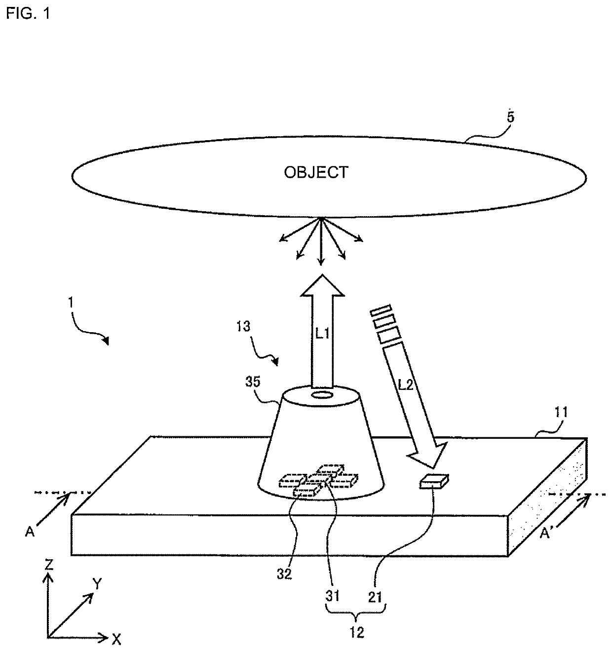
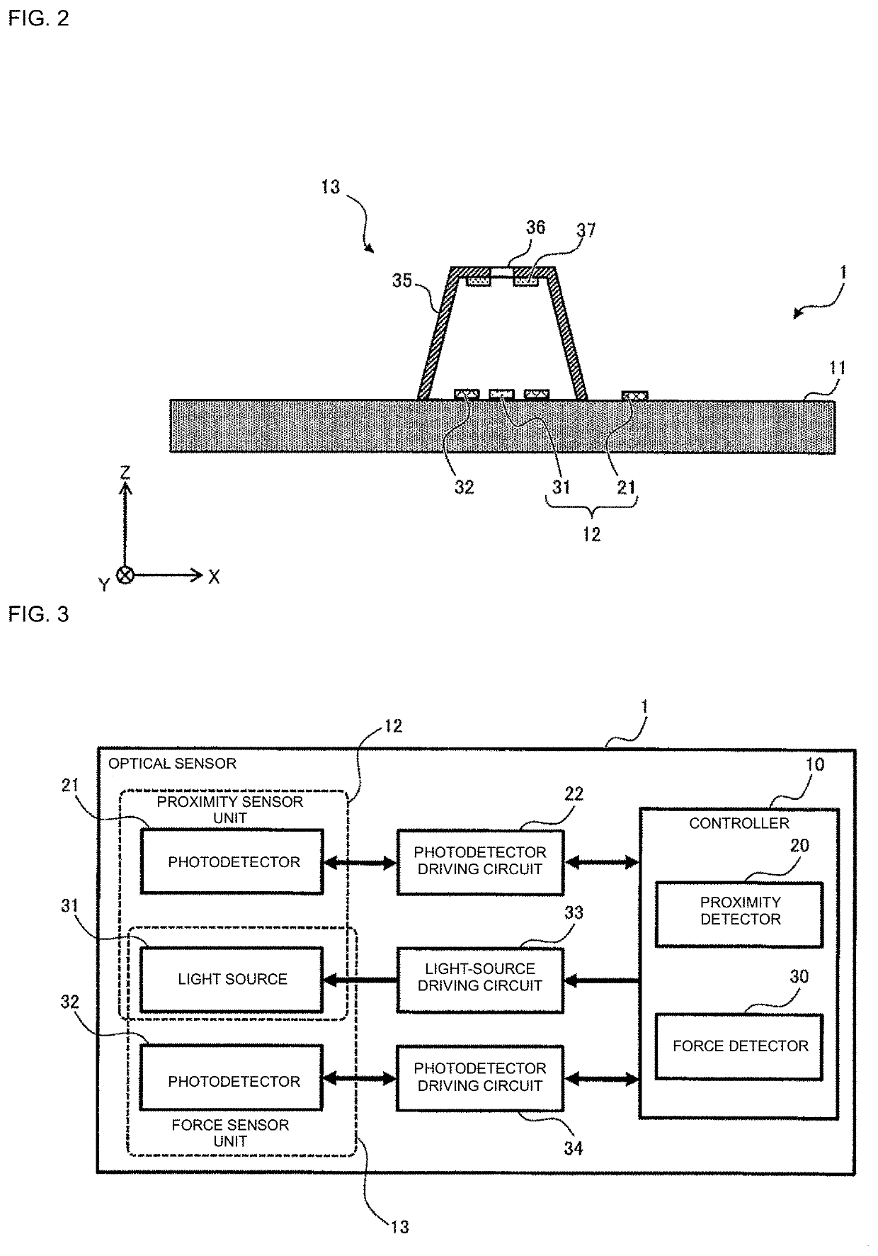
[0024]A configuration of an optical sensor according to a first preferred embodiment of the present invention will be described with reference to FIGS. 1 to 3. FIG. 1 is an illustration for providing an overview of an optical sensor 1 according to the present preferred embodiment.

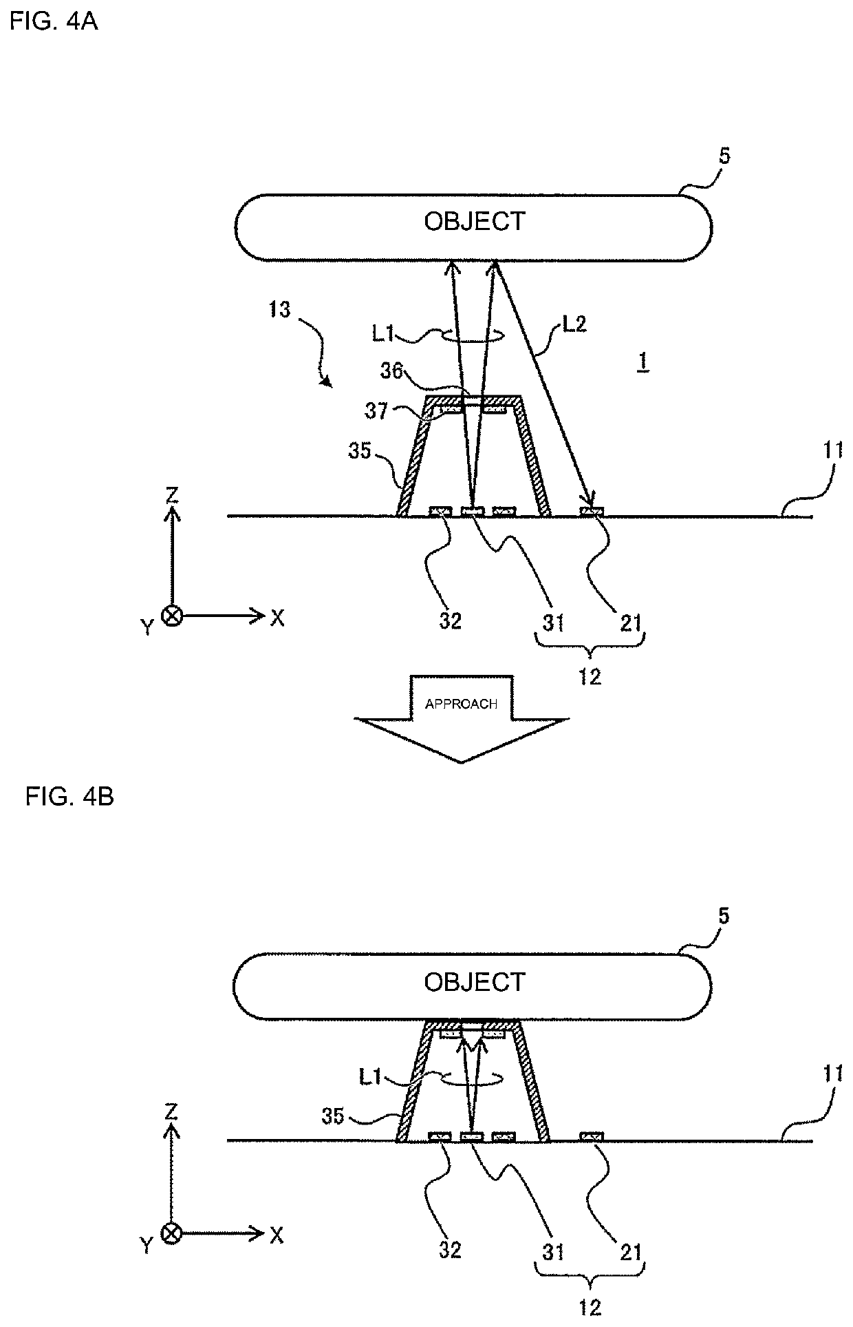
[0025]The optical sensor 1 according to the present preferred embodiment is a module based on an optical detection scheme, and the module includes a proximity sensor 12 and a force sensor 13 that are integrated into a single unit. The proximity sensor 12 is configured to detect an object 5 being in proximity, and the force sensor 13 is configured to detect a force exerted by contact with the object 5 (that is, a contact force). The optical sensor can be used to detect the object 5, which is an example of various objects to be grasped by a robot hand. The proximity sensor 12 and the force sensor 13 of the optical sensor 1 are able to continuously monitor a series of processes in which, for ex...

second preferred embodiment

[0080]In a second preferred embodiment of the present invention, an optical sensor in which a photodetector is shared between a proximity sensor and a force sensor will be described with reference to FIGS. 7 to 9.

[0081]FIG. 7 is an illustration for describing an optical sensor 1A according to the second preferred embodiment. The optical sensor 1A according to the present preferred embodiment has a configuration similar to the configuration described in the first preferred embodiment (refer to FIG. 1) except that a light source 23 is included instead of the photodetector 21 outside the dome 35. A proximity sensor 12A in the optical sensor 1A according to the present preferred embodiment includes the light source 23 outside the dome 35 and the photodetector 32 shared with the force sensor 13. The light source 31 in the force sensor 13 is not shared with the proximity sensor 12A in the present preferred embodiment.

[0082]FIG. 8 is a block diagram of a configuration of the optical sensor...


PUM

PropertyMeasurementUnit
modulation frequencyaaaaaaaaaa

Abstract

An optical sensor includes a first light source to emit light, a first photodetector to receive light and generate a signal representing a result of receiving the light, a cover made of an elastic material deformable in response to an external force and covering the first light source and the first photodetector, the cover including a reflective portion that reflects light and a transmissive portion that transmits light, a force detector to detect a force corresponding to deformation of the cover based on a signal from the first photodetector, the signal representing a result of receiving light emitted by the first light source, an optical assembly outside the covering component, and a proximity detector to detect the object being in proximity by using the optical assembly and one of the first light source and the first photodetector.

Description

CROSS REFERENCE TO RELATED APPLICATIONS[0001]This application claims the benefit of priority to Japanese Patent Application No. 2019-218538 filed on Dec. 3, 2019 and is a Continuation application of PCT Application No. PCT / JP2020 / 035547 filed on Sep. 18, 2020. The entire contents of each application are hereby incorporated herein by reference.BACKGROUND OF THE INVENTION1. Field of the Invention[0002]The present invention relates to an optical sensor to optically detect an object in proximity to the optical sensor and a force exerted by contact with the object.2. Description of the Related Art[0003]In recent years, various sensors to be fitted to a device such as a robot hand have been proposed to enable various types of sensing such as detection of an object in proximity to the sensor or detection of contact with an object (see, for example, Japanese Patent No. 508977, Japanese Patent No. 5825604, and International Publication No. 2014 / 045685).[0004]Japanese Patent No. 5089774 discl...

Claims


Application Information

Patent Timeline
Patent Type & Authority Applications(United States)
IPC IPC(8): G01S17/04G01L1/04
CPCG01S17/04G01L1/04G01V8/20G01L5/166
Inventor KATO, TAKATOSHIWATANABE, HIROSHISUGAHARA, KOHEIAOKI, YUTA
Owner MURATA MFG CO LTD
Why Eureka
Try Eureka