Current transmission assembly and current transmission system

a current transmission system and current transmission technology, applied in the direction of coupling contact members, coupling device connections, multiple conductor connectors, etc., can solve the problems of gradually insufficient current transmission assemblies in the conventional techniqu

Pending Publication Date: 2022-09-08
BELLWETHER ELECTRONICS KUNSHAN +1
View PDF8 Cites 0 Cited by
  • Summary
  • Abstract
  • Description
  • Claims
  • Application Information

AI Technical Summary

Problems solved by technology

A maximum current that can be carried by the terminal structure of conventional current transmission assemblies is related to a design of the terminal structure and a size of a cross-sectional area thereof With an increasing demand for electricity in products, there are also demands for a higher maximum current that can be carried by the terminals, and the current transmission assemblies in the conventional technique have gradually become insufficient.

Method used


Image

  • Current transmission assembly and current transmission system
  • Current transmission assembly and current transmission system
  • Current transmission assembly and current transmission system

Examples


first embodiment

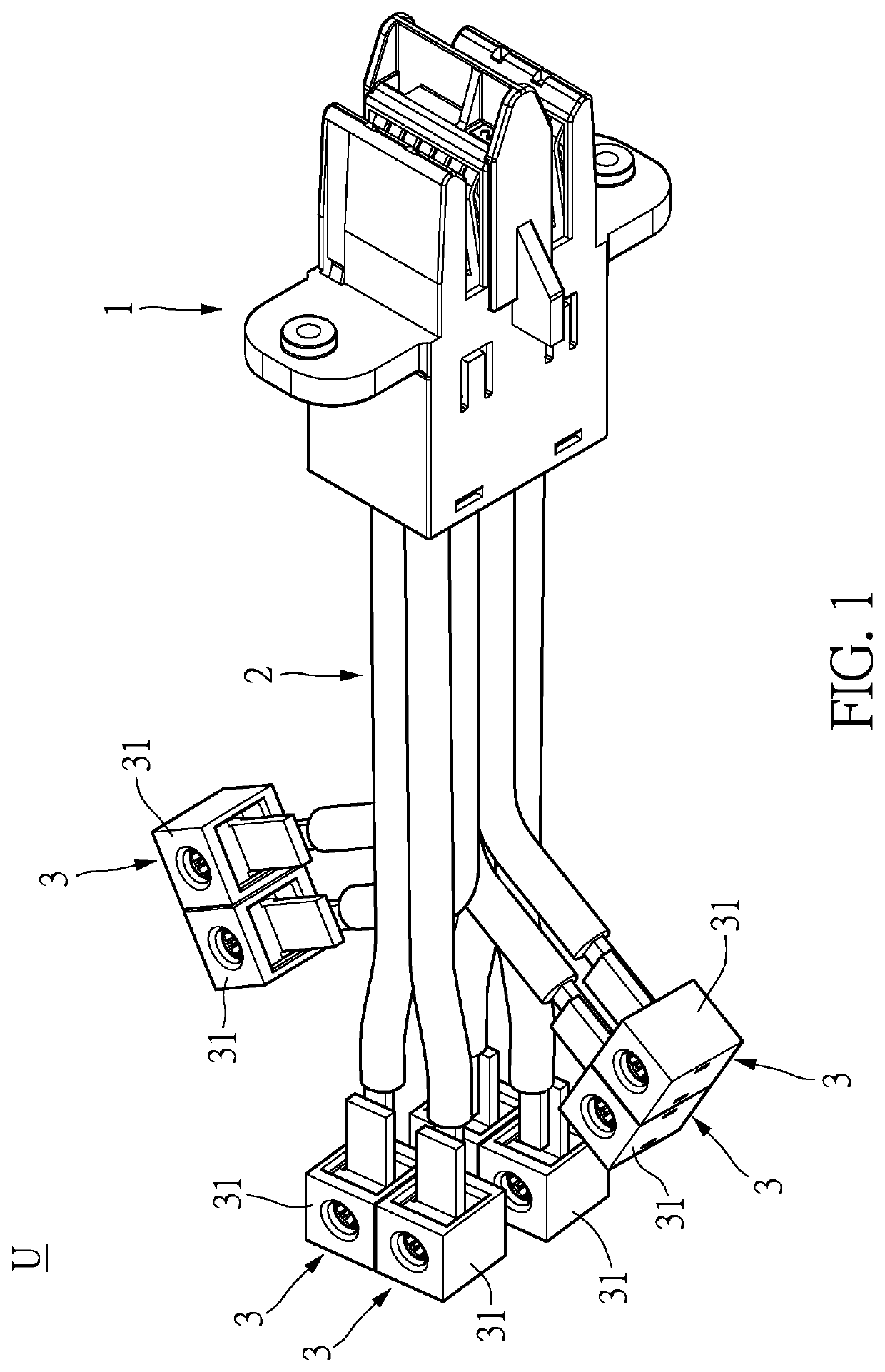
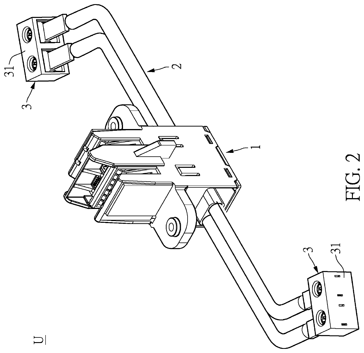
[0038]Referring to FIG. 1, a first embodiment of the present disclosure provides a current transmission assembly U, which can be applied in a power distribution architecture of a data center. The current transmission assembly U includes a pluggable component 1, at least one conductor component 2, and at least one electrically connecting component 3. It is worth mentioning that the current transmission assembly U shown in FIG. 1 is a current transmission structure that extends in one direction, but the present disclosure is not limited thereto. For example, the current transmission assembly U can also be a current transmission structure that extends bilaterally as shown in FIG. 2. In addition, it should be noted that, in the present disclosure, one of the electrically connecting components 3 can correspond to one or more of the conductor components 2 at the same time, or one of the conductor components 2 can correspond to one or more of the electrically connecting components 3 at the...

second embodiment

[0048]Referring to FIG. 11, the present disclosure further provides a current transmission system S according to the current transmission assembly U described above. The current transmission system S includes a current transmission assembly U and a circuit board structure M.

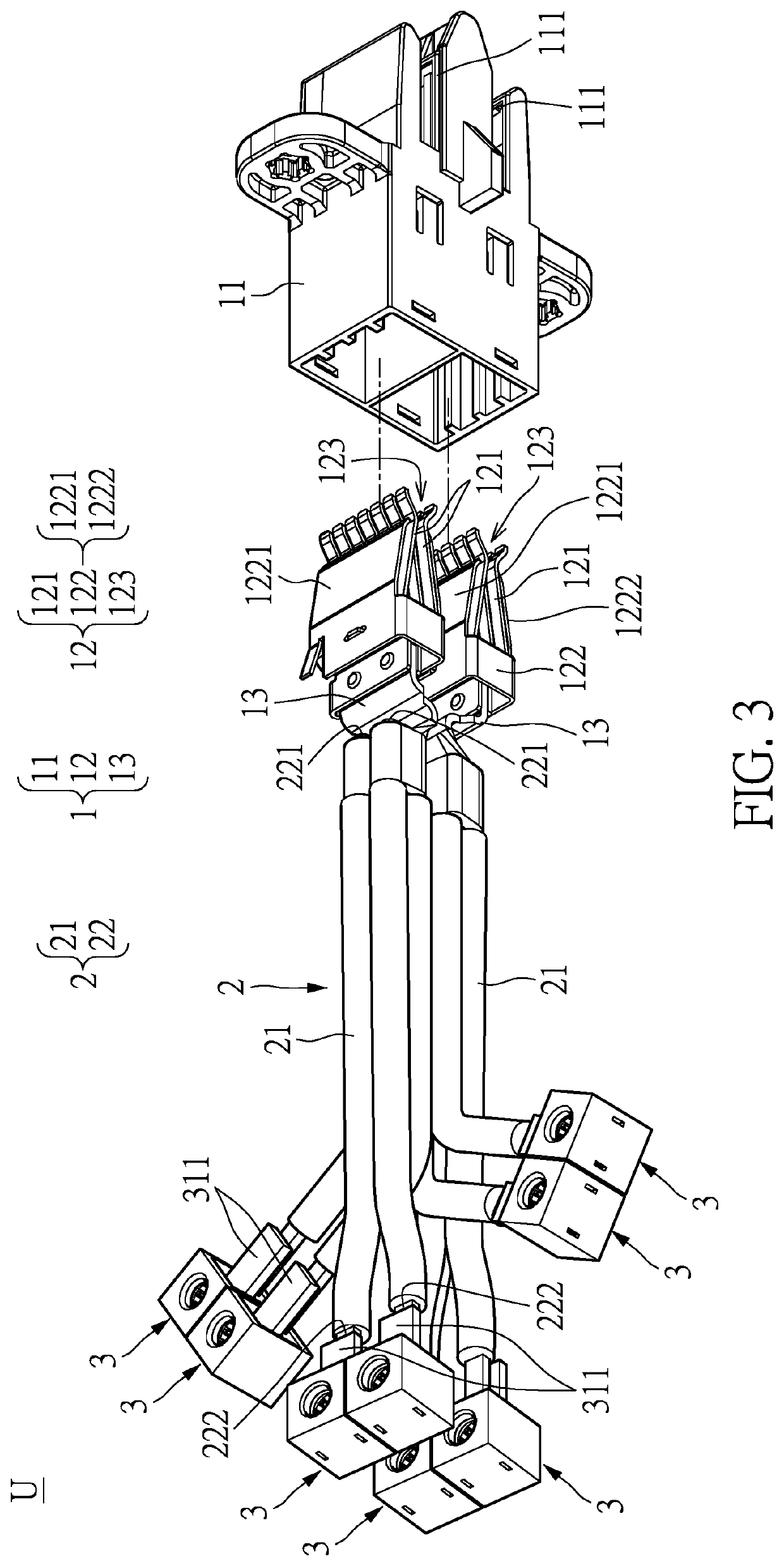
[0049]Specifically speaking, the current transmission assembly U includes a pluggable component 1, at least one conductor component 2, and a first electrically connecting component U1. Specific structures of the pluggable component 1 and the conductor component 2 can be referred to in FIG. 2 and FIG. 3. The pluggable component 1 is a busbar clip terminal structure, which mainly includes a housing 11, two sets of electrically conductive arms 12, and two connecting members 13. The two sets of electrically conductive arms 12 and the two connecting members 13 are both disposed inside the housing 11. The housing 11 includes two sockets 111, and each of the two sets of electrically conductive arms 12 includes two conta...


PUM


Abstract

A current transmission assembly and a current transmission system are provided. The current transmission system includes the current transmission assembly and a circuit board structure. The current transmission assembly includes a pluggable component, at least one conductor component, and at least one electrically connecting component. The pluggable component includes a housing, two sets of electrically conductive arms, and two connecting members. Each of the two sets of electrically conductive arms is disposed inside the housing. Each of the conductor components includes an electrical insulator and a wire main body. The electrical insulator encircles the wire main body, so that a first terminal and a second terminal are exposed from the wire main body, and the first terminal is connected to one of the two connecting members. Each of the electrically connecting components includes a connecting portion, to which the second terminal of the wire main body is fixed.

Description

CROSS-REFERENCE TO RELATED PATENT APPLICATION[0001]This application claims the benefit of priority to China Patent Application No. 202110251146.3, filed on Mar. 8, 2021 in People's Republic of China. The entire content of the above identified application is incorporated herein by reference.[0002]Some references, which may include patents, patent applications and various publications, may be cited and discussed in the description of this disclosure. The citation and / or discussion of such references is provided merely to clarify the description of the present disclosure and is not an admission that any such reference is “prior art” to the disclosure described herein. All references cited and discussed in this specification are incorporated herein by reference in their entireties and to the same extent as if each reference was individually incorporated by reference.FIELD OF THE DISCLOSURE[0003]The present disclosure relates to a current transmission assembly and a current transmission ...

Claims


Application Information

Patent Timeline
Patent Type & Authority Applications(United States)
IPC IPC(8): H01R13/11H01R13/518H01R13/24H01R4/02H01R13/506
CPCH01R13/111H01R13/518H01R13/113H01R13/2492H01R4/023H01R13/506H01R9/22H01R11/32H01R13/02H01R13/112H01R11/05H01R13/187H01R11/28H01R13/41
Inventor CHANG, CHING-HSIANGTANG, XIANG-BIAOCHEN, YEN-LIN
Owner BELLWETHER ELECTRONICS KUNSHAN
Why Eureka
Try Eureka