Driver with open output protection

a technology of output protection and driver, which is applied in the direction of electric variable regulation, process and machine control, instruments, etc., can solve the problems of damage to electronic components, high voltage over output buffer capacitors, and high voltage over output terminals, and achieves good protection performance and low number of components.

Active Publication Date: 2020-08-25
SIGNIFY HLDG BV
View PDF11 Cites 0 Cited by
  • Summary
  • Abstract
  • Description
  • Claims
  • Application Information

AI Technical Summary

Benefits of technology

[0003]An object of the present invention is to provide a switched-mode driver with overvoltage / open load protection having a relatively low number of components and having good protection performance.
[0008]Further, the second one of the output terminals connects to the first end of said first inductor via a diode forwarded from the second one of the output terminals. This embodiment can prevent the supply from providing the startup current to the controllable switching element.
[0010]Further, the load driver further comprises an output buffer capacitor across the first one of the output terminals and the first end of said first inductor. The output buffer capacitor is for smoothing the power provided to the load and reducing ripple.
[0013]In a further embodiment, converter circuit further comprises: a third inductor electromagnetically coupled to said first inductor and coupled to said controllable switching element, said third inductor is adapted to being inductive of a high voltage in response to an over voltage on said first inductor and to turn off said switching element. This embodiment provides an over voltage protection against the open load after the driver has been started. Moreover, the combination of the open protection and the over voltage protection provides a hot-wiring function in which the load can be taken away and then put back during the operation and the load would continue work normally.

Problems solved by technology

In case the driven LED is defective to provide an open circuit, or no LED is connected to the output terminals, the voltage over the output buffer capacitor may become very high, and thus the voltage over the output terminals may become very high, which is potentially dangerous and may cause damage to the electronic components.
Known protection circuits comprise a relatively large number of components and are hence relatively costly.
Additionally, the current open protection circuit starts and stops alternatively and results in burping of the driver: re-start again and again.

Method used


Image

  • Driver with open output protection
  • Driver with open output protection
  • Driver with open output protection

Examples


Embodiment Construction

[0030]Although the present invention relates to a driver for any type of load, the driver is especially useful for application as an LED driver, and hereinafter the present invention will be specifically explained and illustrated for the example of an LED load, without this example reducing the scope of the invention to LEDs.

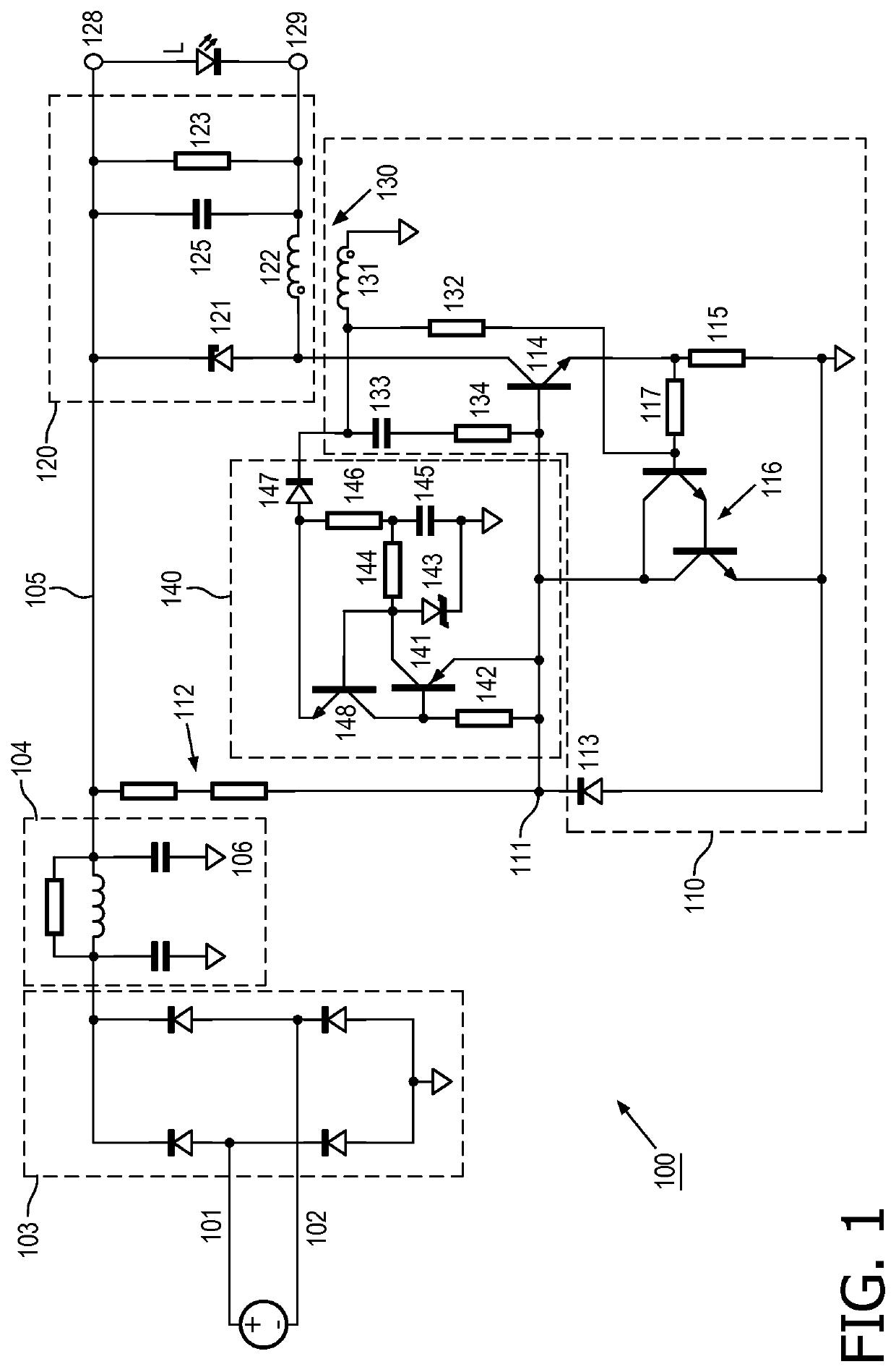
[0031]FIG. 1 schematically shows a circuit diagram of a current driver 100 design. The driver 100 has input terminals 101, 102 for connecting to an AC mains, a rectifying stage 103 and an input filter stage 104. An output side of the input filter stage 104 connects to a positive voltage bus 105 and a negative or ground voltage bus 106. Block 110 is a converter circuit. It comprises a reference node 111 that is connected to the positive voltage bus 105 via a first resistor 112 and to the ground voltage bus 106 via a first diode 113, the cathode terminal of the first diode 113 being connected to the reference node 111.

[0032]In the converter circuit 110, a first NP...


PUM


Abstract

A load driver for driving a load and an LED module are disclosed. In one embodiment, the load driver comprises a converter circuit comprising a controllable switching element configured to be turned on and off and to perform power factor correction for power from a power supply to the load, wherein a control terminal of the controllable switching element is configured for receiving a startup current via the two output terminals, the controllable switching element configured to be turned on by the startup current. The converter circuit further comprises a first inductor, coupled to the power supply at a first end, and to ground at a second end via the controllable switching element, wherein a first one of the output terminals connects to a second end of the first inductor via a diode forwarded from the first inductor, a second one of the output terminals is coupled to the first end of the first inductor.

Description

FIELD OF THE INVENTION[0001]The present invention relates in general to a switched-mode driver. Particularly, but not exclusively, the present invention relates to a switched-mode driver for use as an LED driver.BACKGROUND OF THE INVENTION[0002]In switched-mode drivers, such as those used for driving an LED, an output buffer capacitor is repeatedly charged and discharged. In case the driven LED is defective to provide an open circuit, or no LED is connected to the output terminals, the voltage over the output buffer capacitor may become very high, and thus the voltage over the output terminals may become very high, which is potentially dangerous and may cause damage to the electronic components. Known protection circuits comprise a relatively large number of components and are hence relatively costly. For example, numerous transistors, stabilivolt, capacitors, and other components may be used for sensing the voltage of a secondary transformer winding which is indicative of the load ...

Claims


Application Information

Patent Timeline
Patent Type & Authority Patents(United States)
IPC IPC(8): H05B33/08H05B45/50H02M3/156H02M1/36H02M1/42H05B44/00
CPCH02M3/1563H05B45/50Y02B20/30H02M1/36Y02B70/10H02M1/4225H05B45/56H05B47/24
Inventor CHEN, ZHI QUANLI, DUO L.LI, KANGMA, MATT J.ZHANG, HUICLAESSENS, DENNIS JOHANNES ANTONIUS
Owner SIGNIFY HLDG BV
Why Eureka
Try Eureka