
Optical devices

Pending Publication Date: 2022-09-15
VISERA TECH CO LTD
View PDF6 Cites 0 Cited by
  • Summary
  • Abstract
  • Description
  • Claims
  • Application Information

AI Technical Summary

Benefits of technology

The present invention provides a grating structure in an image sensor that improves the reception of infrared light and reduces crosstalk. The grating structure is designed to filter out infrared light while still allowing other wavelengths to pass through. Additionally, the invention allows for the reproduction of all necessary image information in each target pixel, resulting in more realistic colors.

Problems solved by technology

But this degrades the visible image quality due to lateral crosstalk.

Method used


Image

  • Optical devices
  • Optical devices
  • Optical devices

Examples


Embodiment Construction

[0046]The optical device of the present invention is described in detail in the following description. In the following detailed description, for purposes of explanation, numerous specific details and embodiments are set forth in order to provide a thorough understanding of the present disclosure. The specific elements and configurations described in the following detailed description are set forth in order to clearly describe the present disclosure. It will be apparent, however, that the exemplary embodiments set forth herein are used merely for the purpose of illustration, and the inventive concept may be embodied in various forms without being limited to those exemplary embodiments. In addition, the drawings of different embodiments may use like and / or corresponding numerals to denote like and / or corresponding elements in order to clearly describe the present disclosure. However, the use of like and / or corresponding numerals in the drawings of different embodiments does not sugge...


PUM


Abstract

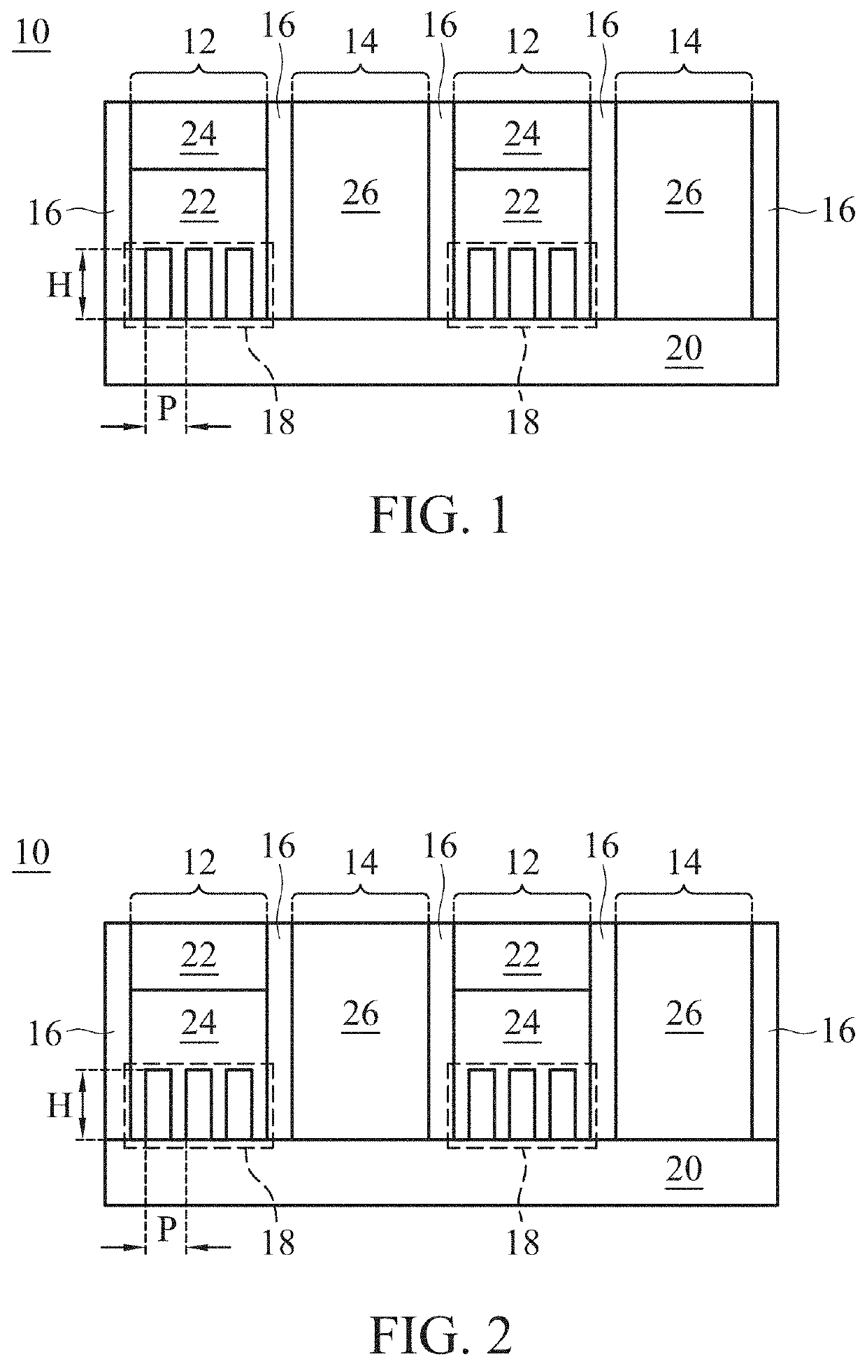
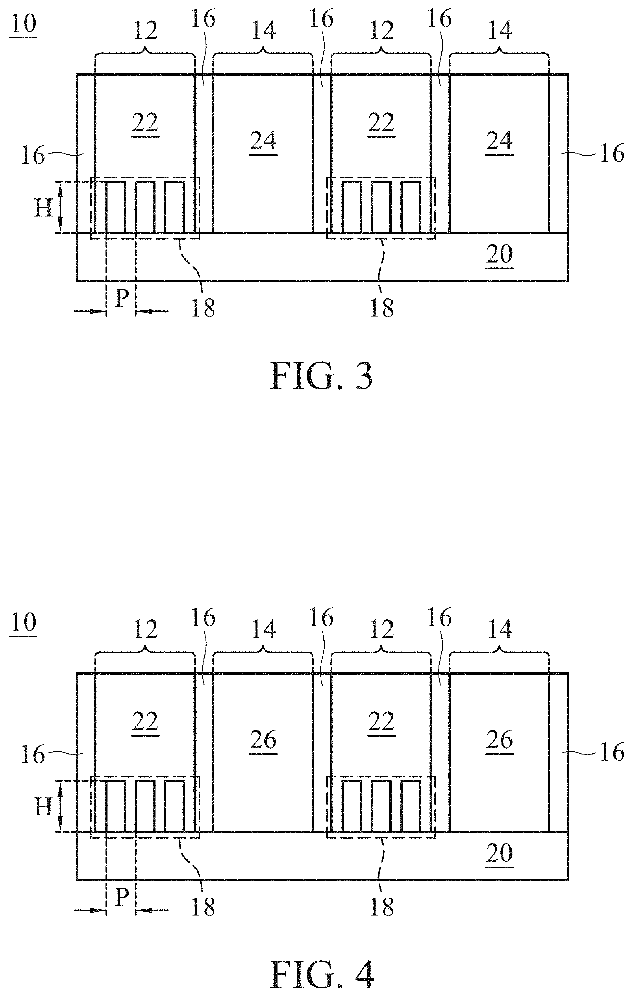
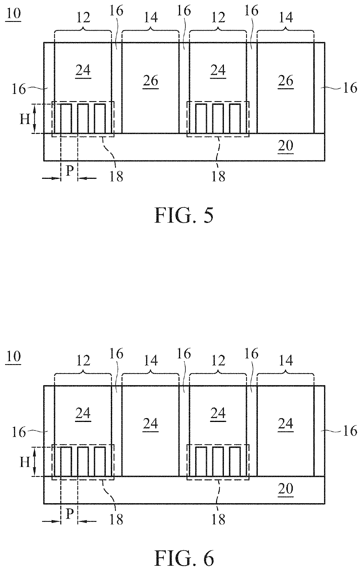
An optical device is provided. The optical device includes a plurality of IR-cut pixels, a plurality of IR-pass pixels, and a plurality of grids. The grids surround the IR-cut pixels and the IR-pass pixels. Each IR-cut pixel includes a first grating structure. A method for fabricating the optical device is also provided.

Description

BACKGROUND OF THE INVENTIONField of the Invention[0001]The invention relates to an optical device, and more particularly to an optical device with a grating structure in an IR-cut pixel.Description of the Related Art[0002]Demand for non-visible, especially near-infrared (NIR) sensitive image sensors for security, personal authentication and range finding applications has been growing. To make image sensors applicable for NIR use, it is important to enhance NIR sensitivity. One approach to improve NIR sensitivity is to arrange IR-pass filters in pixels. But this degrades the visible image quality due to lateral crosstalk.[0003]Therefore, development of an optical device capable of reducing crosstalk is desirable.BRIEF SUMMARY OF THE INVENTION[0004]In accordance with one embodiment of the invention, an optical device is provided. The optical device includes a plurality of IR-cut pixels, a plurality of IR-pass pixels, and a plurality of grids. The grids surround the IR-cut pixels and t...

Claims


Application Information

Patent Timeline
IPC IPC(8): G02B5/20G02B5/18
CPCG02B5/208G02B5/1809G02B5/1819
Inventor TU, ZONG-RU
Owner VISERA TECH CO LTD
Learn More