Capacitively operable MEMS switch

a mems switch and capacitive technology, applied in the direction of relays, electrical equipment, basic electric elements, etc., can solve the problems of low current generation, high current consumption of relays of this type, and relatively high current consumption of most relays

Pending Publication Date: 2022-09-15
ROBERT BOSCH GMBH
View PDF0 Cites 1 Cited by
  • Summary
  • Abstract
  • Description
  • Claims
  • Application Information

AI Technical Summary

Problems solved by technology

Most relays have a relatively high current consumption.
However, relays of this type have a high current consumption because of the required coil.
A disadvantage of a capacitive drive is that only very low forces are able to be generated and these forces do not exhibit a linear characteristic across the deflection.
This behavior according to which the drive force exhibits a reciprocal behavior to the deflection and the restoring force features a linear response thereto is particularly disadvantageous for the switch-off operation of a relay.
Thus, the restoring force is always restricted in this system, which leads to a slow switch-off operation and has a negative effect on the service life of the component.

Method used


Image

  • Capacitively operable MEMS switch
  • Capacitively operable MEMS switch
  • Capacitively operable MEMS switch

Examples


Embodiment Construction

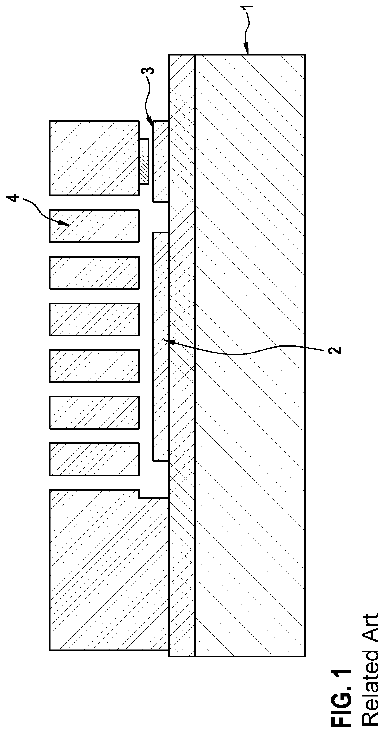
[0028]FIG. 1 schematically shows a sectional view of an electrically operable MEMS switch in the related art. A first electrode 2 and a first contact area 3 are provided on a substrate 1. A lever structure 4 is situated above both structures and separated by a gap. If a voltage is applied between the lever and the first electrode, then a movement out of the substrate plane=(out-of-plane) occurs. The lever is essentially deflected perpendicular to the substrate, and a contact between the lever and a contact area is established.

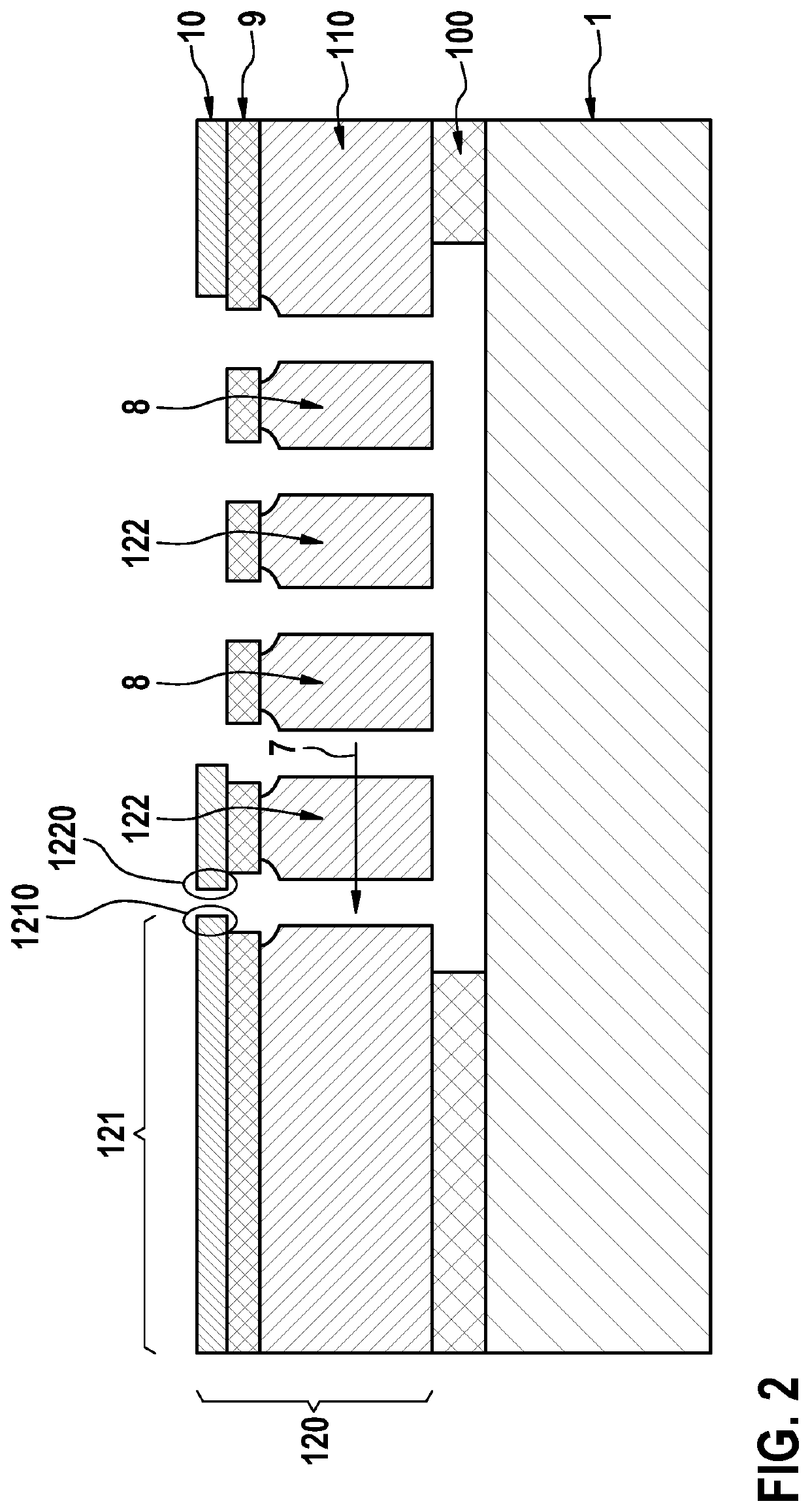
[0029]FIG. 2 schematically shows a sectional view of a capacitively operable MEMS switch having an in-plane switch element. A first insulation layer 100, a silicon layer 110, a second insulation layer 9, and a metal layer 10 are situated on top of one another on a substrate 1. The silicon layer, the second insulation layer and the metal layer jointly form a micromechanical function layer 120 in which a fixed part 121, an electrically operable deflectable switch...


PUM


Abstract

A MEMS switch having a substrate, a micromechanical function layer situated above the substrate, and a fixed part and an electrically operable, deflectable switch element are developed in the micromechanical function layer, the switch element for closing an electrically conductive contact with the fixed part being suspended on at least one first spring in a deflectable manner. In a first operating state, the switch element is in a first position at a first distance from the fixed part, and the electrical contact is open. In a second operating state, the switch element is in a second position at a second distance from the fixed part, and the first spring is deflected and exerts a first restoring force, and the switch element establishes an operative connection with at least one second spring and the electrical contact is open. In a third operating state, the switch element is in a third position.

Description

CROSS REFERENCE[0001]The present application claims the benefit under 35 U.S.C. § 119 of German Patent Application No. DE 10 2021 202 409.2 filed on Mar. 12, 2021, which is expressly incorporated herein by reference in its entirety.BACKGROUND INFORMATION[0002]The present invention relates to an electrically operable MEMS switch having a substrate and a micromechanical function layer situated above the substrate, a fixed part and an electrically operable deflectable switch element being developed in the micromechanical function layer, and the switch element is suspended in a deflectable manner on at least one first spring for closing an electrically conductive contact with the fixed part.[0003]Different types of relays are available in the related art. Most relays have a relatively high current consumption. They are typically driven electromagnetically and require a solenoid coil for their operation. This makes it possible to generate great forces. However, relays of this type have a...

Claims


Application Information

Patent Timeline
Patent Type & Authority Applications(United States)
IPC IPC(8): H01H59/00
CPCH01H59/0009
Inventor REINMUTH, JOCHENLEWIS, MATTHEW
Owner ROBERT BOSCH GMBH
Why Eureka
Try Eureka