
Temperature sensor

Pending Publication Date: 2022-09-29
WLKA ALEXANDER WIEGAND SE & CO KG
View PDF0 Cites 0 Cited by
  • Summary
  • Abstract
  • Description
  • Claims
  • Application Information

AI Technical Summary

Benefits of technology

The present temperature sensor is designed to be less impacted by environmental factors and has a fast response time and high accuracy. It uses different materials for the conductors which creates a thermocouple that is more sensitive to changes in the environment and can detect and monitor those changes with greater precision and reliability.

Problems solved by technology

Either is extremely cost-intensive, as a process plant usually has to be powered down first, i.e., shut down.
However, it has been shown that in particular thermocouples for surface temperature measurements in the high-temperature measuring range cannot be sufficiently adjusted by this method.
Thus, the reference points are far away from the actual working range, so that the calibration is not optimal.
Apart from this, impairments in the thermocouples or thermowires could be present in these applications, which for methodological reasons cannot be corrected by this in-situ calibration.

Method used


Image

  • Temperature sensor
  • Temperature sensor
  • Temperature sensor

Examples


Embodiment Construction

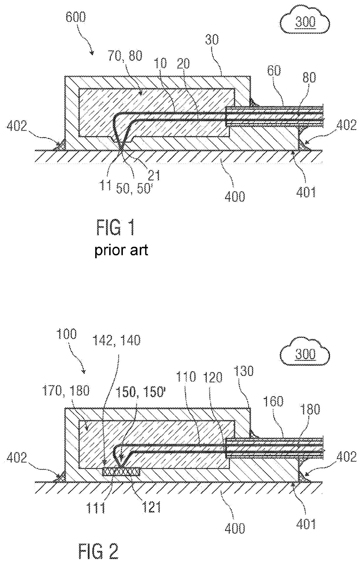
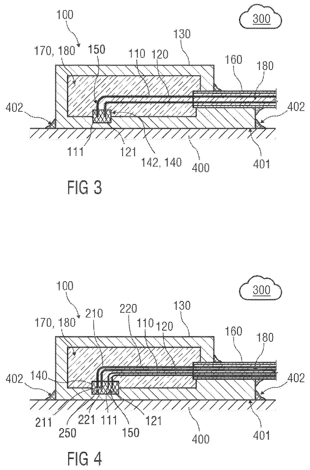
[0060]FIG. 1 shows a sectional representation of a temperature sensor 600 as it is known from the prior art. A first conductor 10 comprising an end section 11 and a second conductor 20 comprising an end section 21 are led to a casing 30 by means of a sheathed thermocouple 60. The sheathed thermocouple 60 is inserted into an opening of the casing 30 and welded to be sealed to the casing 30. This means that the opening of the casing 30 is sealed tightly by the sheathed thermocouple 60 welded into it. Both the sheathed thermocouple 60 as well as a free internal volume 70 of the casing 30 are filled with a mineral or ceramic insulating material 80, for example a powder. The conductors 10, 20 formed of different materials, are led to a contact point 50′ in the casing 30 and there form a thermocouple 50 by a connection of their end sections 11, 21. In this example, the first conductor 10 and the second conductor 20 are welded to a thin section of a casing wall. Thus, the thermocouple 50 i...


PUM


Abstract

A temperature sensor, having a first conductor made of a first material comprising an end section, a second conductor made of a second material, which differs from the first material, comprising an end section, and a casing for receiving the end sections of the two conductors and for positioning in a process atmosphere or in a process fluid and / or on a surface of a process structure. According to the invention, a measuring point body structure is provided, which is arranged within the casing or on the casing, wherein the first conductor and the second conductor directly or indirectly form a thermocouple in or on the measuring point body structure and the measuring point body structure comprises a barrier material.

Description

[0001]This nonprovisional application claims priority under 35 U.S.C. § 119(a) to German Patent Application No. 10 2021 107 608.0, which was filed in Germany on Mar. 25, 2021, and which is herein incorporated by reference.BACKGROUND OF THE INVENTIONField of the Invention[0002]The present invention relates to a temperature sensor comprising a thermocouple, in particular for a high temperature measurement.Description of the Background Art[0003]Such temperature sensors are generally known from the prior art.[0004]For example, a thermocouple temperature sensor for measuring the temperature of a surface is known from U.S. Pat. No. 5,141,335 A. The thermocouple wires, also referred to as thermowires, are guided here with an insulating material in a sheathed thermocouple to a casing part. The sheathed thermocouple is inserted into an opening of the casing and welded to be sealed. The thermocouple wires are guided within the casing part to a measuring point at the bottom of the casing and w...

Claims


Application Information

Patent Timeline
IPC IPC(8): G01K7/06
CPCG01K7/06G01K7/02G01K1/08G01K1/143G01K13/02H10N10/17H10N10/80H10N10/81H10N10/817
Inventor STAAB, ULRICH
Owner WLKA ALEXANDER WIEGAND SE & CO KG
Learn More