Welding helmet

a helmet and head technology, applied in the field of welding helmets, can solve the problems of wearer's head being covered in dirt and other fragments, wearer's discomfort, wearer's bumping or scraping,

Pending Publication Date: 2022-10-06
3M INNOVATIVE PROPERTIES CO
View PDF0 Cites 0 Cited by
  • Summary
  • Abstract
  • Description
  • Claims
  • Application Information

AI Technical Summary

Problems solved by technology

Therefore, it is not uncommon for the wearer's head to be covered in dirt and other fragments from the workpiece.
It is also not uncommon for the wearer to bump or scrape their head on hard or sharp objects from the workpiece.
These known bump caps are often heavy, large an

Method used


Image

  • Welding helmet
  • Welding helmet
  • Welding helmet

Examples


Embodiment Construction

[0045]Unless explicitly stated otherwise, all embodiments and optional features of the present disclosure can be combined freely.

[0046]The disclosure will now be described, by way of example only, and with reference to the following drawings, in which:

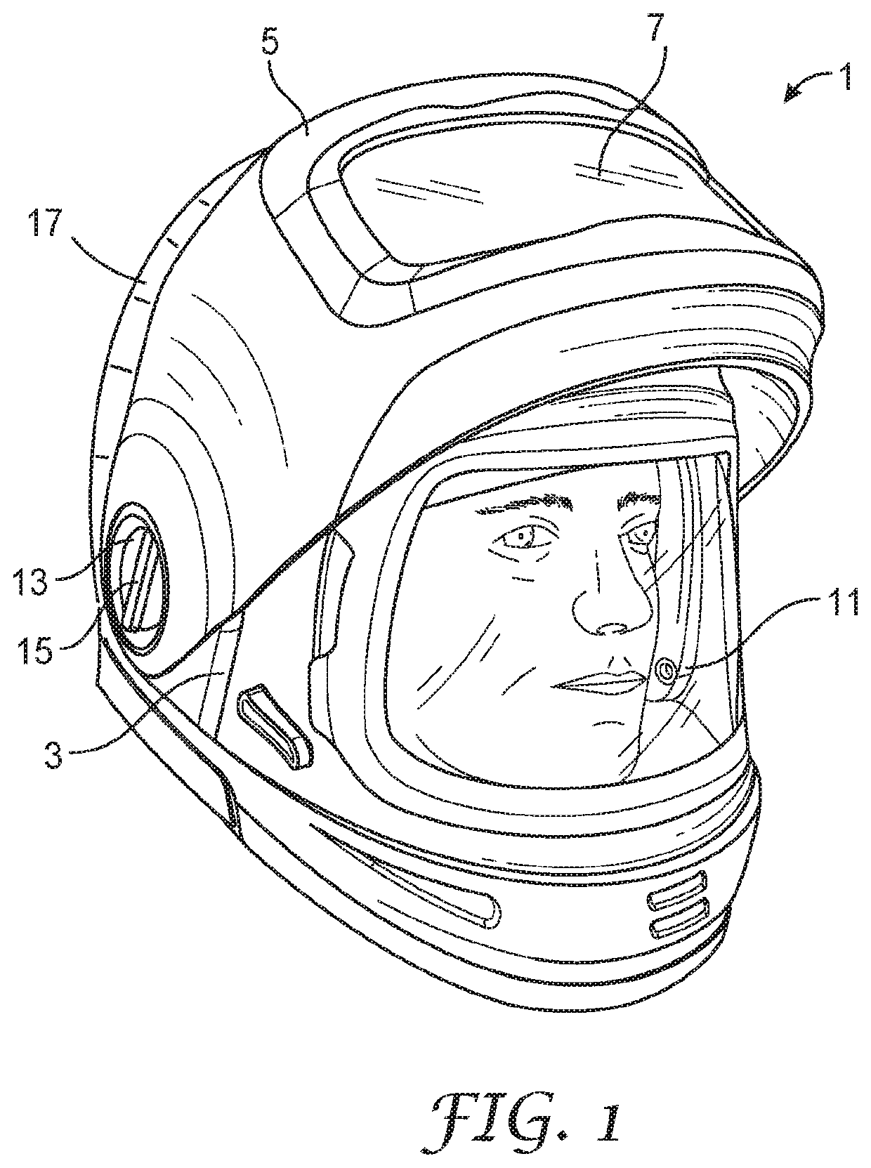
[0047]FIG. 1 is a perspective view of a welding helmet;

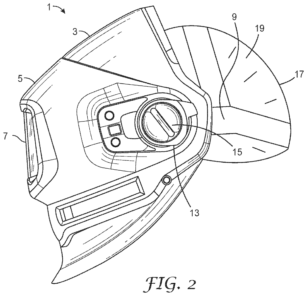
[0048]FIG. 2 is a side view of the welding helmet of FIG. 1;

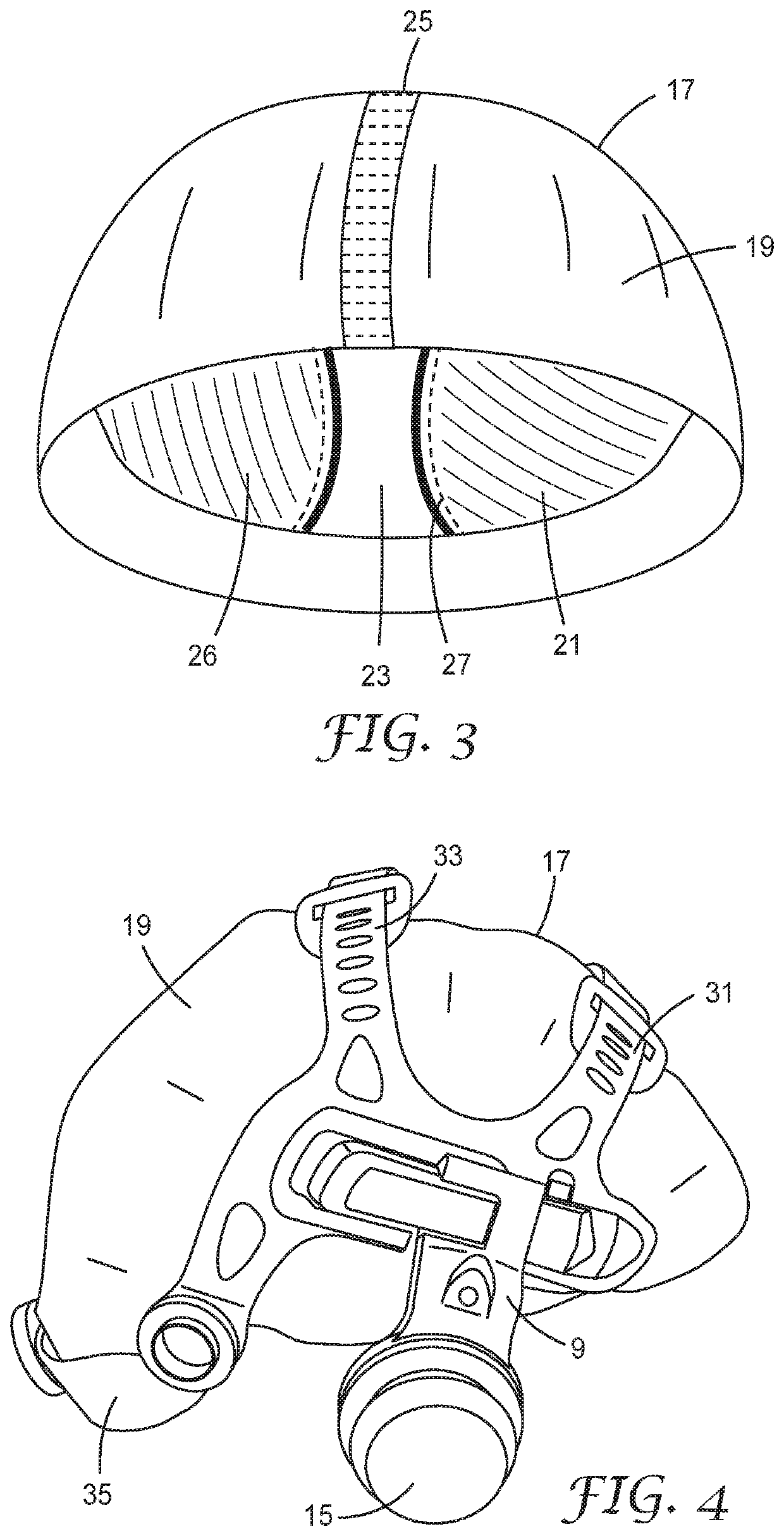
[0049]FIG. 3 is a perspective view of the protective cap according to this disclosure;

[0050]FIG. 4 is a side view of a protective cap and a head suspension system according to this disclosure;

[0051]FIG. 5 is another view of the protective cap of FIG. 4,

[0052]FIG. 6 is a cross section of the protective cap with the flexible outer layer and compressible inner liner attached to the inside surface of the flexible outer layer, and

[0053]FIG. 7 is another perspective view of the protective cap,

[0054]FIG. 1 shows a welding helmet 1 which has a face protection member 3 illustrated in a lowered position and a moveable visor 5 illust...


PUM


Abstract

There is provided a welding helmet (1) comprising a face protection member (3) moveable between a lowered position in which the face protection member (3) covers a wearer's face, and an upraised position, in which the face protection member (3) uncovers the wearer's face, a headband suspension system (9) for fixing the face protection member (3) to a wearer's head, a protective cap (17) comprising a flexible outer layer (19) and at least one compressible inner liner (21).

Description

TECHNICAL FIELD[0001]The present disclosure relates to a welding helmet comprising a face protection member moveable between a lowered position in which the face protection member covers a wearer's face, and an upraised position, in which the face protection member uncovers the wearer's face, a headband suspension system for fixing the face protection member to a wearer's head.BACKGROUND OF THE DISCLOSURE[0002]Welding Helmets are typically used in the mechanical and industrial art to protect wearers from harmful irradiation emitted from the welding arc and from splashes, sparks and particles that may be ejected from a welding area. Welding helmets typically can be suspended on the head of a wearer, so that the wearer has both hands available for welding and handling of workpieces.[0003]Some welding helmets are furnished with an automatic darkening filter. An automatic darkening filter commonly has a switchable filter that automatically changes from a light-state to a dark-state in r...

Claims


Application Information

Patent Timeline
IPC IPC(8): A42B3/10A42B3/22A61F9/06
CPCA42B3/10A42B3/225A61F9/067A61F9/02
Inventor DANIELS, BJÖRN
Owner 3M INNOVATIVE PROPERTIES CO
Why Eureka
Try Eureka