Recirculation of lubricant in a turbomachine rolling-element bearing

a technology of rolling-element bearings and turbomachines, which is applied in the direction of bearing components, shafts, shafts, etc., can solve the problems of affecting the performance of the engine, affecting the overall cost of the engine, so as to achieve simple, effective and economical solutions.

Pending Publication Date: 2022-10-06
SAFRAN POWER UNITS
View PDF0 Cites 0 Cited by
  • Summary
  • Abstract
  • Description
  • Claims
  • Application Information

AI Technical Summary

Benefits of technology

[0005]The invention offers a simple, effective and economical solution to this problem by means of a beari

Problems solved by technology

This external lubrication system degrades the performance of the engine (in particular in terms of specific power and reliability) and represe

Method used


Image

  • Recirculation of lubricant in a turbomachine rolling-element bearing
  • Recirculation of lubricant in a turbomachine rolling-element bearing
  • Recirculation of lubricant in a turbomachine rolling-element bearing

Examples


Embodiment Construction

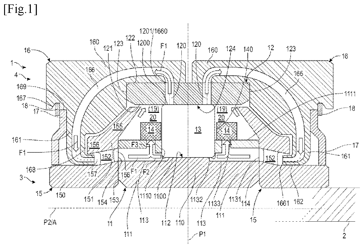
[0035]FIG. 1 shows a schematic cross-section of the portion of a recirculating bearing 1 located on a first side of a rotational axis A of the bearing 1. The bearing 1 is for example mounted on a shaft 2.

[0036]In general, in the following description, the terms “longitudinal” and “axial” refer to the orientation of structural elements extending in the direction of the axis of rotation A. The term “radial” refers to an orientation of structural elements extending in a direction perpendicular to the axis of rotation A.

[0037]Furthermore, when the cross-section of an annular element is described, reference is made only to the portion on one side of the axis of rotation A of the bearing 1, the other portion being obtained by mirror image with respect to the axis A in the plane of the figures, for example.

[0038]The bearing 1 comprises an internal ring 3, an external ring 4, a plurality of rolling-elements 13. The internal ring 3 and the external ring 4 are intended to pivot relative to ea...


PUM


Abstract

Rolling-element bearing for a turbomachine of an aircraft, comprising an inner ring (3) defining a first raceway (112), and an outer ring (4) defining a second raceway (124), characterized in that the bearing has at least one loop circuit (21, 22) for forced recirculation of lubricant, this loop circuit comprising a first recirculation circuit (21) comprising at least one lubricant inlet (1200) located on the second raceway (124), and connected by at least one duct (120, 166) created in the outer ring (4) to at least one lubricant outlet (1661) which discharges into a second recirculation circuit (22) of the loop circuit (21, 22), this second recirculation circuit (22) comprising at least one duct (152, 1134, 1136; 1135, 1136) created in the inner ring (3).

Description

TECHNICAL FIELD OF THE INVENTION[0001]The invention relates to a rolling-element bearing for a turbomachine, in particular for an aircraft, this bearing comprising a lubricant recirculation circuit.BACKGROUND[0002]The gas generators such as those used for the aeronautical auxiliary power units, or other types of devices using small turbomachines, typically have bearings for their rotating shafts, provided with rolling-elements that are subject to a lubrication. To ensure this lubrication, an external lubrication system is provided, which comprises a pump, a distribution circuit, and various components such as valves and solenoid valves. This external lubrication system degrades the performance of the engine (in particular in terms of specific power and reliability) and represents a significant part of the overall cost of the engine.[0003]The lubricant (oil or grease) used to lubricate a bearing of this type is injected into the bearing and helps lubricate it for a limited period of ...

Claims


Application Information

Patent Timeline
IPC IPC(8): F16C33/66
CPCF16C33/6681F16C33/6677F16C2360/23
Inventor COT, SERGE MARIE GABRIELLOPEZ, JEAN-PAUL SALVADORCHEVALIER, STEPHANE
Owner SAFRAN POWER UNITS
Why Eureka
Try Eureka