Supercharge Your Innovation With Domain-Expert AI Agents!

System and method for utilizing patient-specific emission-based body contour detection

a technology of emission-based emission, which is applied in the field of system and method for utilizing patient-specific emission-based body contour detection, can solve the problems of large contour, long scan time, and poor photon count projections,

Pending Publication Date: 2022-10-13
GE PRECISION HEALTHCARE LLC
View PDF6 Cites 0 Cited by
  • Summary
  • Abstract
  • Description
  • Claims
  • Application Information

AI Technical Summary

Benefits of technology

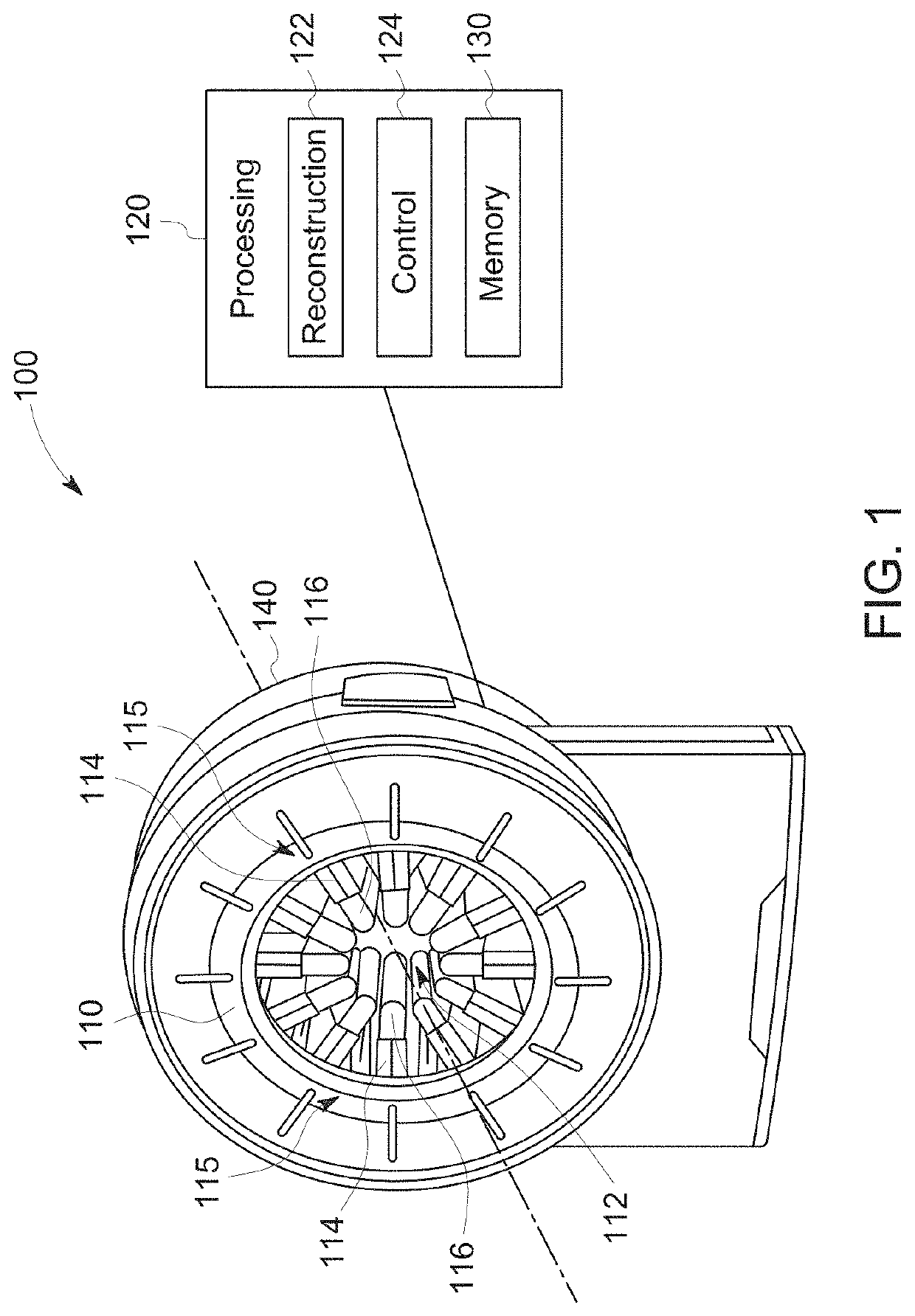
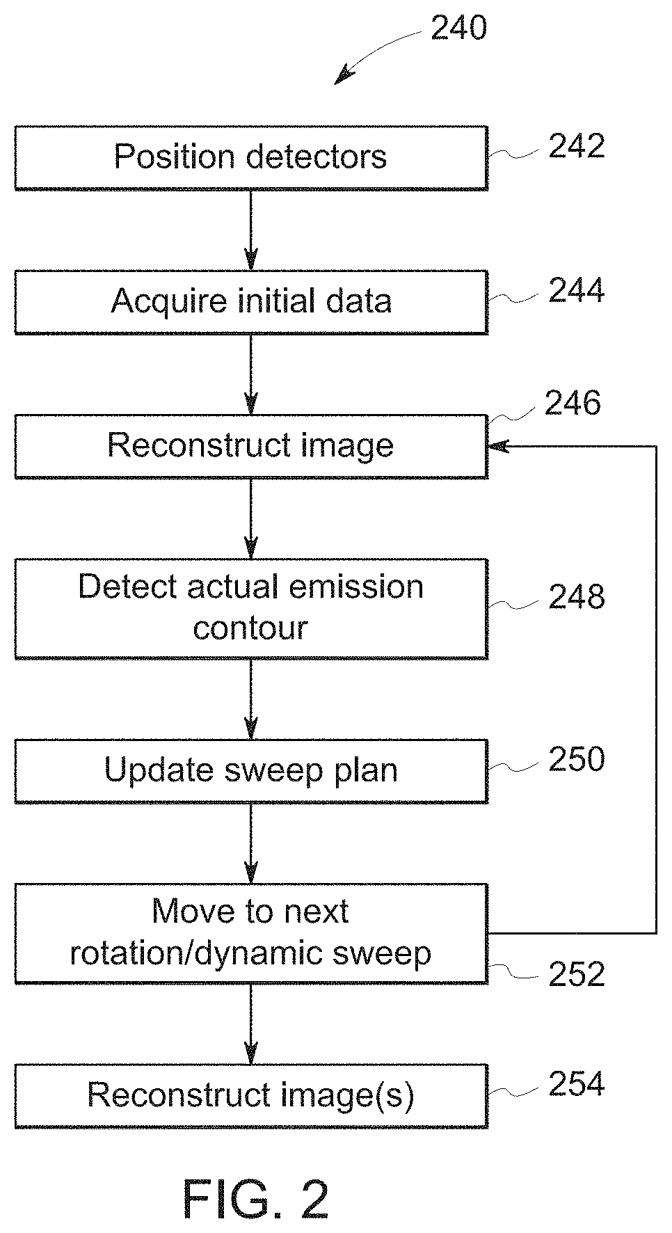
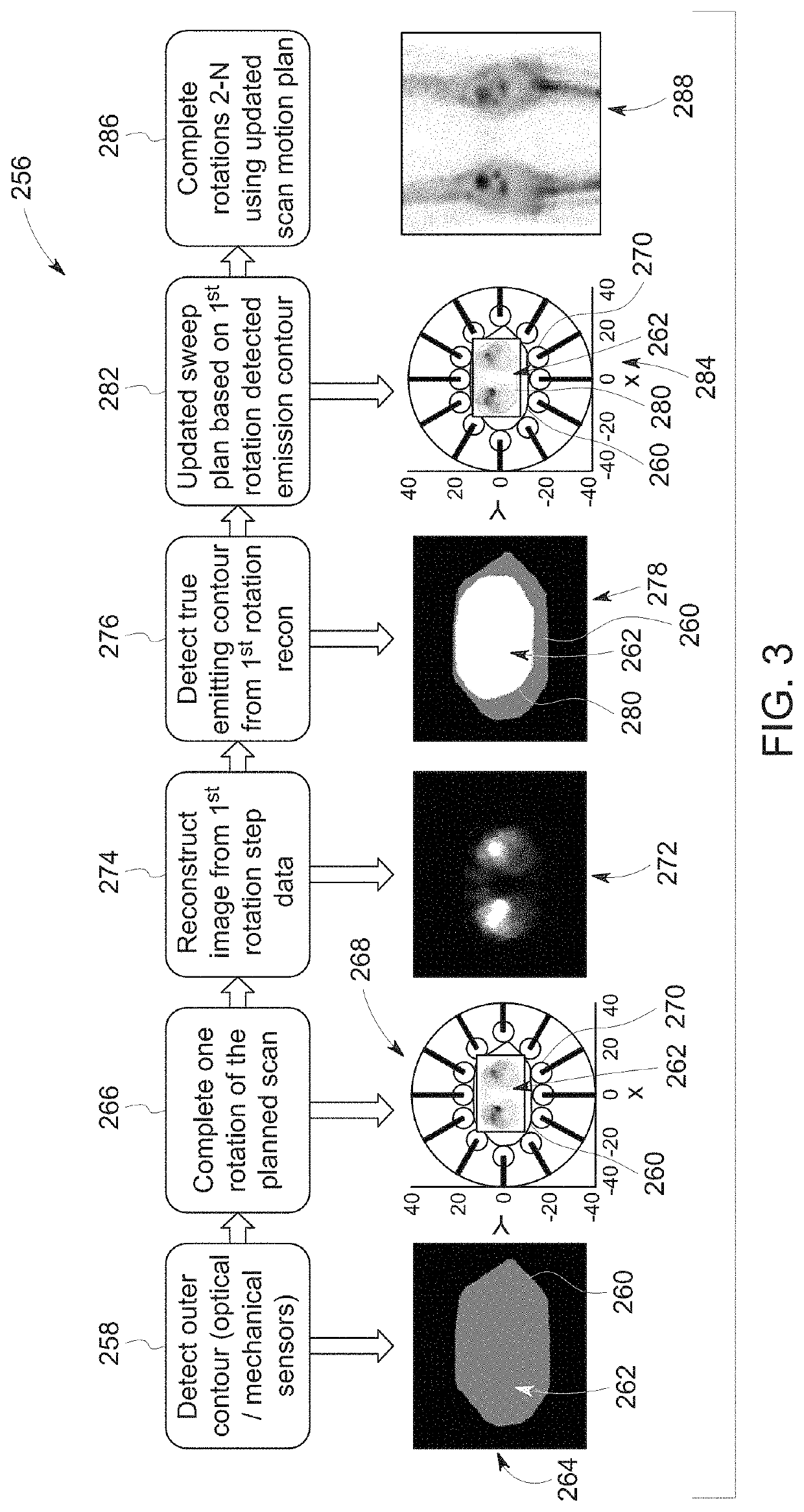
The patent describes a nuclear medicine multi-head imaging system and a method for using it to acquire and detect the actual emission contour of an object during a scan. The system can then update the scan sweep plan based on the detected contour for the remaining portion of the scan. The technical effect of this patent is to provide a more precise and accurate means for imaging objects using a nuclear medicine multi-head imaging system.

Problems solved by technology

However, in many cases, the physical contour is larger, sometimes significantly, than the active emitting body contour, due to items (e.g., clothing, blankets, extending tubes, mechanical obstructions, patient table, etc.) that add to the acquired contour size.
This causes some of the views to be acquired out of the range of the actual emitting body contour, resulting in projections with poor photon counts and negligible contribution to image quality.
In addition, scans are longer than necessary due to the acquisition of these views out of the range of the actual emitting body contour.

Method used


Image

  • System and method for utilizing patient-specific emission-based body contour detection
  • System and method for utilizing patient-specific emission-based body contour detection
  • System and method for utilizing patient-specific emission-based body contour detection

Examples


Embodiment Construction

[0016]One or more specific embodiments will be described below. In an effort to provide a concise description of these embodiments, not all features of an actual implementation are described in the specification. It should be appreciated that in the development of any such actual implementation, as in any engineering or design project, numerous implementation-specific decisions must be made to achieve the developers' specific goals, such as compliance with system-related and business-related constraints, which may vary from one implementation to another. Moreover, it should be appreciated that such a development effort might be complex and time consuming, but would nevertheless be a routine undertaking of design, fabrication, and manufacture for those of ordinary skill having the benefit of this disclosure.

[0017]When introducing elements of various embodiments of the present subject matter, the articles “a,”“an,”“the,” and “said” are intended to mean that there are one or more of th...


PUM


Abstract

An imaging system is provided that includes a gantry defining a bore configured to accept an object to be imaged, wherein the gantry is configured to rotate about the bore. The system includes multiple detector units mounted to the gantry and configured to rotate with the gantry around the bore in rotational steps, each detector unit configured to sweep about a corresponding axis and acquire imaging information while sweeping about the corresponding axis. The system includes at least one processor operably coupled to at least one of the detector units that is configured to acquire, during an initial portion of a scan, imaging information of the object based on an initial contour and to detect an actual emission contour based on the imaging information. The processor is configured to update a scan sweep plan based on the detected actual emission contour for a remaining portion of the scan.

Description

BACKGROUND[0001]The subject matter disclosed herein relates to medical imaging systems and, more particularly, to radiation detection systems.[0002]In nuclear medicine (NM) imaging, such as single photon emission computed tomography (SPECT) or positron emission tomography (PET) imaging, radiopharmaceuticals are administered internally to a patient. Detectors (e.g., gamma cameras), typically installed on a gantry, capture the radiation emitted by the radiopharmaceuticals and this information is used, by a computer, to form images. The NM images primarily show physiological function of, for example, the patient or a portion of the patient being imaged.[0003]An NM imaging system may be configured as a multi-head imaging system having several individual detectors distributed about the gantry. Each detector (e.g., detector head) may pivot or sweep to provide a range over which the detector may acquire information that is larger than a stationary field of view of the detector. In a multi-...

Claims


Application Information

Patent Timeline
Patent Type & Authority Applications(United States)
IPC IPC(8): A61B6/00G06T7/13G06T11/00A61B6/03
CPCA61B6/545G06T7/13G06T11/008A61B6/037A61B6/4266G06T2207/20116G06T2211/412G06T11/005A61B6/4258G06T7/12G06T2207/30196G06T2207/10081G06T2207/10108G01B11/2433
Inventor MERMAN, MICHAL MARIAGROBSHTEIN, YARIV
Owner GE PRECISION HEALTHCARE LLC
Features
  • R&D
  • Intellectual Property
  • Life Sciences
  • Materials
  • Tech Scout
  • Unparalleled Data Quality
  • Higher Quality Content
  • 60% Fewer Hallucinations
Learn More