System for driving power devices

Pending Publication Date: 2022-10-13
DELTA ELECTRONICS SHANGHAI CO LTD
0 Cites 1 Cited by

AI-Extracted Technical Summary

Problems solved by technology

In addition, since the length specifications of the wires are identical, th...

Method used

[0029]Since the first driving terminals 31 on the gate plates 3 are corresponding to the second driving terminals 61 on the control board 4 one-to-one, the wires for connecting the first driving terminal 31 and the second driving terminal 61 can be arranged in a specific sequence with the same length. Therefore, the parasitic parameters between the wires are controllable, and thus the consistency of driving the power devices connected in parallel and the reliability of multi-level circuit are enhanced. In addition, since the length specifications of the wires are identical, the difficulty of sample preparation, installation and maintenance decreases. Further, the wires do not need to be interlaced, thereby overcoming the problems about electromagnetic interference and insulation.
[0034]All the first semiconductor modules 211-21n and all the second semiconductor modules 221-22n are alternately arranged on the heat dissipation plate 1 and are disposed at the first side 41 of the control board 4. Through arranging all of the first semiconductor modules 211-21n and the second semiconductor modules 221-22n alternately on the heat dissipation plate 1, the circuit loop may be shortened, the circuit inductance may be reduced, and the overall performance of the system will be enhanced. All the third semiconductor module 231-23n are arranged on the heat dissipation plate 1 in sequence and are disposed at the second side 42 of the control board 4. The second side 42 is opposite to the first side 41. A first part of the driving bridge plates 51 (i.e., the driving bridge plates 51 corresponding to the first and second semiconductor modules 211-21n and 221-22n) and a first part of the second driving terminals 61 (i.e., the second driving terminals 61 corresponding to the first and second semiconductor modules 211-21n and 221-22n) are disposed adjacent to the first side 41 of the control board 4. A second part of the driving bridge plates 51 (i.e., the driving bridge plates 51 corresponding to the third semiconductor modules 231-23n) and a second part of the second driving terminals 61 (i.e., the second driving terminals 61 corresponding to the third semiconductor modules 231-23n) are disposed adjacent to the second side 42 of the control board 4. In addition, the first part of the driving bridge plates 51 are arranged in a sequence based on the magnitude of electric potential, and the second part of the driving bridge plates 51 are arranged in a sequence based on the magnitude of electric potential, thereby reducing the electric potential difference between the adjacent driving bridge plates 51.
[0038]In an embodiment, every signal transmitted by the driving bridge plate 51, the first protection bridge plate 52 or the second protection bridge plate 53 has an interference sensitivity. The signal with lower interference sensitivity is easier to be interfered. According to a descending order of the interference sensitivity of the transmitted signals, the first part of the driving bridge plates 51 and the first protection bridge plate 52 are arranged sequentially in a direction from the center of the control board 4 to the first side 41. The second part of the driving bridge plates 51 and the second protection bridge plate 53 are arranged sequentially in a direction from the center of the control board 4 to the second side 42. The first protection bridge plate 52 is for example but not limited to be located on the inner side of the first part of the driving bridge plates 51. The second protection bridge plate 53 is for example but not limited to be located on the inner side of the second part of the driving bridge plates 51. Consequently, the signals transmitted by the bridge module 5 can be prevented from being interfered by the radiation from power lines. In an embodiment, in order to further prevent the signals transmitted by the bridge module 5 from being interfered, the system further includes a first separating plate and a second separating plate (not shown). The first separating plate is disposed between the first part of the driving bridge plates 51 and the first part of the second driving terminals 61. The second separating plate is disposed between the second part of the driving bridge plates 51 and the second part of the second driving terminals 61. The first and second separating plates both include a grounded shielding layer for preventing the signals transmitted by the bridge module 5 from being interfered.
[0039]In above embodiments, the semiconductor modules 2 are disposed at the two sides of the control board 4, but the present disclosure is not limited thereto. In an embodiment, the semiconductor modules 2 may be disposed at one side of the control board 4. As exemplified in FIG. 8, in this embodiment, all the semiconductor modules 2 include a plurality of first semiconductor modules 211, 212, . . . , 21n and a plurality of second semiconductor modules 221, 222, . . . , 22n, and the number of the first semiconductor modules and the number of the second semiconductor modules are the same. Each of the first semiconductor modules 211, 212, . . . , 21n and the second semiconductor modules 221, 222, . . . , 22n includes at least one power device. The power devices at the corresponding position in the first semiconductor modules 211, 212, . . . , 21n are connected to each other in parallel, and the power devices at the corresponding position in the second semiconductor modules 221, 222, . . . , 22n are connected to each other in parallel. For example, each of the first semiconductor modules 211, 212, . . . , 21n includes a power device S1 and a power device S2. The power devices S1 of the first semiconductor modules 211, 212, . . . , 21n are connected to each other in parallel, and the power devices S2 of the first semiconductor modules 211, 212, . . . , 21n are connected to each other in parallel. Likewise, each of the second semiconductor modules 221, 222, . . . , 22n includes a power device S1 and a power device S2. The power devices S1 of the second semiconductor modules 221, 222, . . . , 22n are connected to each other in parallel, and the power devices S2 of the second semiconductor modules 221, 222, . . . , 22n are connected to each other in parallel. All the first semiconductor modules 211-21n and all the second semiconductor modules 221-22n are alternately arranged on the heat dissipation plate 1 and are disposed at the first side 41 of the control board 4. Through arranging all of the first semiconductor modules 211-21n and the second semiconductor modules 221-22n alternately on the heat dissipation plate...

Benefits of technology

[0012]The present disclosure provides a system for driving power devices. In this system, the driving terminals on gate plates are corresponding to the driving terminals on control board one-to-one so that the wires for connecting the driving terminals can be arranged in specific sequence and have the same length. Therefore, the parasitic parameters between the wires are controllable, and thus the ...

Abstract

A system for driving power devices is provided, and the system includes a heat dissipation plate, semiconductor modules, gate plates, a control board, a bridge module, and a terminal module. The semiconductor modules are disposed on the heat dissipation plate. Each gate plate is disposed on the corresponding semiconductor module and includes first driving terminal. The control board is disposed on the heat dissipation plate. The bridge module and the terminal module are electrically connected to each other, disposed on the control board, and arranged sequentially in a direction from a center to an edge of the control board. The bridge module includes a plurality of driving bridge plates, and each driving bridge plate is electrically coupled to the control board. The terminal module includes a plurality of second driving terminals, and each second driving terminal is electrically connected to the corresponding driving bridge plate and first driving terminal.

Application Domain

Semiconductor/solid-state device detailsConversion constructional details +4

Technology Topic

PhysicsEngineering +2

Image

  • System for driving power devices
  • System for driving power devices
  • System for driving power devices

Examples

  • Experimental program(1)

Example

[0027]The present disclosure will now be described more specifically with reference to the following embodiments. It is to be noted that the following descriptions of preferred embodiments of this disclosure are presented herein for purpose of illustration and description only. It is not intended to be exhaustive or to be limited to the precise form disclosed.
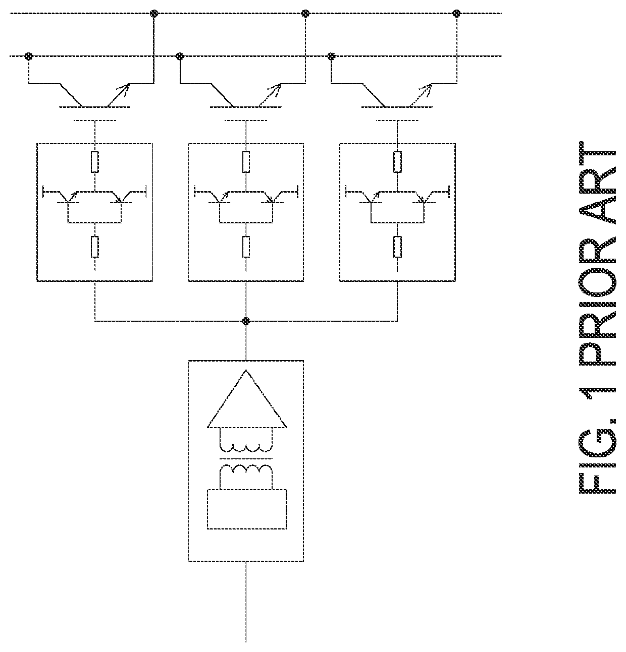
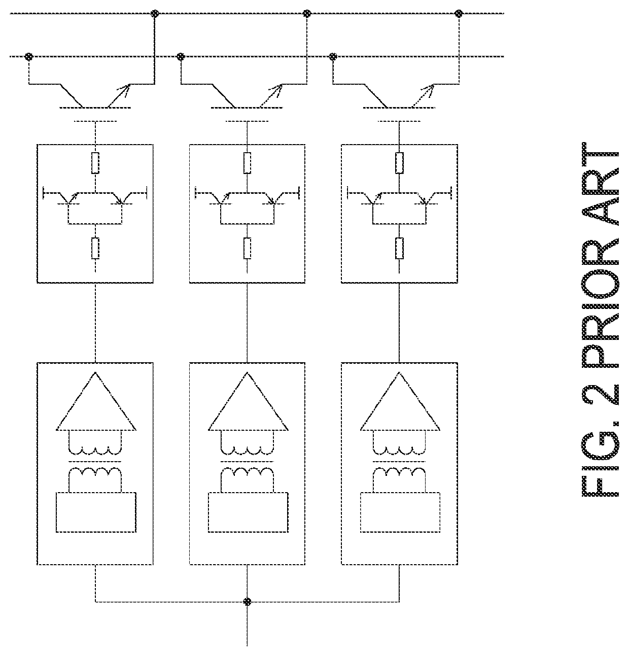
[0028]FIG. 5A is a schematic perspective view illustrating a system for driving power devices according to an embodiment of the present disclosure, FIG. 5B is a schematic perspective view illustrating the system for driving power devices of FIG. 5A from another viewpoint, and FIG. 5C schematically shows a top view of the system for driving power devices of FIG. 5A. As shown in FIG. 5A, FIG. 5B and FIG. 5C, the system for driving power devices includes a heat dissipation plate 1, a plurality of semiconductor modules 2, a plurality of gate plates 3, a control board 4, a bridge module 5, and a terminal module 6. The plurality of semiconductor modules 2 are disposed on the heat dissipation plate 1 and are corresponding to the plurality of gate plates 3 one-to-one. Each gate plate 3 is disposed on the corresponding semiconductor module 2 and includes at least one first driving terminal 31. The control board 4 is disposed on the heat dissipation plate 1 and is configured to provide driving signals for driving the semiconductor modules 2. The bridge module 5 and the terminal module 6 are electrically connected to each other and are both disposed on the control board 4. Further, the bridge module 5 and the terminal module 6 are arranged sequentially in a direction from the center to the edge of the control board 4. The edge of the bridge module 5 is parallel to the edge of the control board 4. The bridge module 5 includes a plurality of driving bridge plates 51, and each driving bridge plate 51 is electrically coupled to the control board 4. The terminal module 6 includes a plurality of second driving terminals 61, and the plurality of second driving terminals 61 are corresponding to all the first driving terminals 31 one-to-one. Each second driving terminal 61 is electrically connected to the corresponding driving bridge plate 51 and first driving terminal 31.
[0029]Since the first driving terminals 31 on the gate plates 3 are corresponding to the second driving terminals 61 on the control board 4 one-to-one, the wires for connecting the first driving terminal 31 and the second driving terminal 61 can be arranged in a specific sequence with the same length. Therefore, the parasitic parameters between the wires are controllable, and thus the consistency of driving the power devices connected in parallel and the reliability of multi-level circuit are enhanced. In addition, since the length specifications of the wires are identical, the difficulty of sample preparation, installation and maintenance decreases. Further, the wires do not need to be interlaced, thereby overcoming the problems about electromagnetic interference and insulation.
[0030]In an embodiment, the system further includes a driving module 7 disposed on the control board 4. The driving module 7, the bridge module 5 and the terminal module 6 are arranged sequentially in the direction from the center to the edge of the control board 4. The driving module 7 includes a plurality of driving boards 71, and each driving board 71 is electrically coupled to the control board 4 and the corresponding driving bridge plate 51. For example, the driving board 71 is electrically coupled to the corresponding driving bridge plate 51 by terminal X1, X2, X3, X4, X5 and X6. As shown in FIG. 6, in this exemplary embodiment, one driving board 71 includes terminals X1 and X2, and terminals X1 and X2 are electrically connected to the corresponding driving bridge plate 51, respectively. Another driving board includes terminals X3 and X4, and the third driving board includes terminals X5 and X6. The driving board is configured to provide the driving signals for driving the semiconductor modules 2. In an embodiment, the driving module 7, the bridge module 5 and the terminal module 6 are coupled to each other through the conductive pattern on the control board 4.
[0031]FIG. 6 is a schematic block diagram illustrating the system for driving power devices according to the embodiment of the present disclosure. As shown in FIG. 6, the semiconductor modules include a plurality of first semiconductor modules 211-21n, a plurality of second semiconductor modules 221-22n and a plurality of third semiconductor modules 231-23n, where n is an integer larger than or equal to 2, and the number of the first, second and third semiconductor modules are the same. As an example, the system shown in FIG. 5A, FIG. 5B and FIG. 5C is the implementation of n equal to 3. The plurality of first semiconductor modules 211-21n are electrically connected to the plurality of second semiconductor modules 221-22n and the plurality of third semiconductor modules 231-23n respectively. Each of the first semiconductor modules 211-21n includes at least one power device, and the power devices at the corresponding position in the first semiconductor modules 211-21n are connected to each other in parallel. For example, the power devices at the corresponding position in the first semiconductor module 211, the first semiconductor module 212 to the first semiconductor module 21n are connected to each other in parallel. Each of the second semiconductor modules 221-22n includes at least one power device, and the power devices at the corresponding position in the second semiconductor modules 221-22n are connected to each other in parallel. For example, the power devices at the corresponding position in the second semiconductor module 221 to the second semiconductor module 22n are connected to each other in parallel. Each of the third semiconductor modules 231-23n includes at least one power device, and the power devices at the corresponding position in the third semiconductor modules 231-23n are connected to each other in parallel. For example, the power devices at the corresponding position in the third semiconductor module 231 to the third semiconductor module 23n are connected to each other in parallel.
[0032]As an example, each of the first semiconductor modules 211-21n includes a power device S1 and a power device S2. The power devices S1 of all the first semiconductor modules 211-21n are connected to each other in parallel, and the power devices S2 of all the first semiconductor modules 211-21n are connected to each other in parallel. Each of the second semiconductor modules 221-22n includes at least one power device, and the power devices at the corresponding position in the second semiconductor modules 221-22n are connected to each other in parallel. As an example, each of the second semiconductor modules 221-22n includes a power device S1 and a power device S2. The power devices S1 of all the second semiconductor modules 221-22n are connected to each other in parallel, and the power devices S2 of all the second semiconductor modules 221-22n are connected to each other in parallel. Each of the third semiconductor modules 231-23n includes at least one power device, and the power devices at the corresponding position in the third semiconductor modules 231-23n are connected to each other in parallel. As an example, each of the third semiconductor modules 231-23n includes a power device S1 and a power device S2. The power devices S1 of all the third semiconductor modules 231-23n are connected to each other in parallel, and the power devices S2 of all the third semiconductor modules 231-23n are connected to each other in parallel. In an embodiment, each of the first semiconductor modules 211-21n, the second semiconductor modules 221-22n and the third semiconductor modules 231-23n includes one power device. The power devices of the first semiconductor modules 211-21n are connected to each other in parallel. The power devices of the second semiconductor modules 221-22n are connected to each other in parallel. The power devices of the third semiconductor modules 231-23n are connected to each other in parallel.
[0033]In an embodiment, the parallel-connected power devices in the first semiconductor modules 211-21n are electrically coupled to the same driving bridge plate. The parallel-connected power devices in the second semiconductor modules 221-22n are electrically coupled to the same driving bridge plate. The parallel-connected power devices in the third semiconductor modules 231-23n are coupled to the same driving bridge plate.
[0034]All the first semiconductor modules 211-21n and all the second semiconductor modules 221-22n are alternately arranged on the heat dissipation plate 1 and are disposed at the first side 41 of the control board 4. Through arranging all of the first semiconductor modules 211-21n and the second semiconductor modules 221-22n alternately on the heat dissipation plate 1, the circuit loop may be shortened, the circuit inductance may be reduced, and the overall performance of the system will be enhanced. All the third semiconductor module 231-23n are arranged on the heat dissipation plate 1 in sequence and are disposed at the second side 42 of the control board 4. The second side 42 is opposite to the first side 41. A first part of the driving bridge plates 51 (i.e., the driving bridge plates 51 corresponding to the first and second semiconductor modules 211-21n and 221-22n) and a first part of the second driving terminals 61 (i.e., the second driving terminals 61 corresponding to the first and second semiconductor modules 211-21n and 221-22n) are disposed adjacent to the first side 41 of the control board 4. A second part of the driving bridge plates 51 (i.e., the driving bridge plates 51 corresponding to the third semiconductor modules 231-23n) and a second part of the second driving terminals 61 (i.e., the second driving terminals 61 corresponding to the third semiconductor modules 231-23n) are disposed adjacent to the second side 42 of the control board 4. In addition, the first part of the driving bridge plates 51 are arranged in a sequence based on the magnitude of electric potential, and the second part of the driving bridge plates 51 are arranged in a sequence based on the magnitude of electric potential, thereby reducing the electric potential difference between the adjacent driving bridge plates 51.
[0035]In an embodiment, the control board 4 includes a processing unit 43, and the bridge module 5 further includes a first protection bridge plate 52 and a second protection bridge plate 53. The first and second protection bridge plates 52 and 53 are electrically connected to the processing unit 43. For example, the first protection bridge plate 52 is electrically connected to the processing unit 43 through terminal X8, and the second protection bridge plate 53 is electrically connected to the processing unit 43 through terminal X7. The driving module 7 may be located between the first and second parts of the driving bridge plates 51, but not limited thereto. Each gate plate 3 further includes a first protection terminal 32. The terminal module 6 further includes a plurality of second protection terminals 62. All the first protection terminals 32 are corresponding to the plurality of second protection terminals 62 one-to-one. In addition, each second protection terminal 62 disposed adjacent to the first side 41 of the control board 4 is electrically connected to the corresponding first protection terminal 32 and the first protection bridge plate 52. Each second protection terminal 62 disposed adjacent to the second side 42 of the control board 4 is electrically connected to the corresponding first protection terminal 32 and the second protection bridge plate 53. In the embodiment shown in FIG. 6, the first and second protection bridge plates 52 and 53 are disposed adjacent to the first side 41 and the second side 42 of the control board 4 respectively. The second protection terminals 62, which are corresponding to the first protection terminals 32 of the gate plates 3 on the first and second semiconductor modules 211-21n and 221-22n, are electrically connected to the first protection bridge plate 52. The second protection terminals 62, which are corresponding to the first protection terminals 32 of the gate plates 3 on the third semiconductor modules 231-23n, are electrically connected to the second protection bridge plate 53. The spacing between the bridge plates can be adjusted according to actual requirements, so as to control the parasitic parameters between the wires.
[0036]In FIG. 6, the wires for connecting the first driving terminals 31 and the second driving terminals 61 are represented by solid lines, and the wires for connecting the first protection terminals 32 and the second protection terminals 62 are represented by dashed lines. The driving bridge plate 51 is configured to receive the corresponding driving signal and distribute the received driving signal into a plurality of gate driving signals. The gate driving signal is transmitted to the gate of the power device in the corresponding semiconductor module through the corresponding first driving terminal 31 and second driving terminal 61, and thus the power devices coupled to the same driving bridge plate are driven to operate synchronously. In the semiconductor modules, the gates of the parallel-connected power devices receive the gate driving signals outputted by the same driving bridge plate respectively. Therefore, in the semiconductor modules, the parallel-connected power devices are turned on or turned off synchronously. For example, the power device S1 in the first semiconductor module 211 and the power device S1 in the first semiconductor module 212 are connected to the same driving bridge plate 51 through the first driving terminals 31 and the second driving terminals 61. The driving bridge plate 51 outputs two gate driving signal to drive the power device S1 in the first semiconductor module 211 and the power device S1 in the first semiconductor module 212 to operate (e.g., turning on or off) synchronously. The power device S2 in the first semiconductor module 211 and the power device S2 in the first semiconductor module 212 are connected to the same driving bridge plate 51 through the first driving terminals 31 and the second driving terminals 61. The driving bridge plate 51 outputs two gate driving signals to drive the power device S2 in the first semiconductor module 211 and the power device S2 in the first semiconductor module 212 to operate (e.g., turning on or off) synchronously.
[0037]Moreover, in FIG. 6, the first driving terminals 31 of the gate plate 3 and the second driving terminals 61 of the terminal module 6 are represented by terminals G1, G2, G3, G4, G5 and G6. The gate driving signals which are transmitted by the first and second driving terminals 31 and 61 represented by the same symbol are the same. The distance between the first and second driving terminals 31 and 61 represented by the same symbol is equal to the same value. For example, the gate driving signals which are transmitted by the terminal G1 of the first driving terminals 31 and the terminal G1 of the second driving terminals 61 are the same, and the distance between the first and second driving terminals 31 and 61 represented by G1 is equal to the same value. In addition, all the first and second protection terminals 32 and 62 are represented by NTC. The protection signal is transmitted from the first protection terminal 32 of the gate plate 3 to the second protection terminal 62 on the control board 4 through the wire. Then, the transmitted protection signals are converged through the first and second protection bridge plates 52 and 53 and then are transmitted to the processing unit 43. In this embodiment, the thermistor RNTC are utilized to collect the temperature signals of the semiconductor modules, and the temperature signals are transmitted to the processing unit 43 for calculating, so as to perform the protecting operation accordingly, but not exclusively.
[0038]In an embodiment, every signal transmitted by the driving bridge plate 51, the first protection bridge plate 52 or the second protection bridge plate 53 has an interference sensitivity. The signal with lower interference sensitivity is easier to be interfered. According to a descending order of the interference sensitivity of the transmitted signals, the first part of the driving bridge plates 51 and the first protection bridge plate 52 are arranged sequentially in a direction from the center of the control board 4 to the first side 41. The second part of the driving bridge plates 51 and the second protection bridge plate 53 are arranged sequentially in a direction from the center of the control board 4 to the second side 42. The first protection bridge plate 52 is for example but not limited to be located on the inner side of the first part of the driving bridge plates 51. The second protection bridge plate 53 is for example but not limited to be located on the inner side of the second part of the driving bridge plates 51. Consequently, the signals transmitted by the bridge module 5 can be prevented from being interfered by the radiation from power lines. In an embodiment, in order to further prevent the signals transmitted by the bridge module 5 from being interfered, the system further includes a first separating plate and a second separating plate (not shown). The first separating plate is disposed between the first part of the driving bridge plates 51 and the first part of the second driving terminals 61. The second separating plate is disposed between the second part of the driving bridge plates 51 and the second part of the second driving terminals 61. The first and second separating plates both include a grounded shielding layer for preventing the signals transmitted by the bridge module 5 from being interfered.
[0039]In above embodiments, the semiconductor modules 2 are disposed at the two sides of the control board 4, but the present disclosure is not limited thereto. In an embodiment, the semiconductor modules 2 may be disposed at one side of the control board 4. As exemplified in FIG. 8, in this embodiment, all the semiconductor modules 2 include a plurality of first semiconductor modules 211, 212, . . . , 21n and a plurality of second semiconductor modules 221, 222, . . . , 22n, and the number of the first semiconductor modules and the number of the second semiconductor modules are the same. Each of the first semiconductor modules 211, 212, . . . , 21n and the second semiconductor modules 221, 222, . . . , 22n includes at least one power device. The power devices at the corresponding position in the first semiconductor modules 211, 212, . . . , 21n are connected to each other in parallel, and the power devices at the corresponding position in the second semiconductor modules 221, 222, . . . , 22n are connected to each other in parallel. For example, each of the first semiconductor modules 211, 212, . . . , 21n includes a power device S1 and a power device S2. The power devices S1 of the first semiconductor modules 211, 212, . . . , 21n are connected to each other in parallel, and the power devices S2 of the first semiconductor modules 211, 212, . . . , 21n are connected to each other in parallel. Likewise, each of the second semiconductor modules 221, 222, . . . , 22n includes a power device S1 and a power device S2. The power devices S1 of the second semiconductor modules 221, 222, . . . , 22n are connected to each other in parallel, and the power devices S2 of the second semiconductor modules 221, 222, . . . , 22n are connected to each other in parallel. All the first semiconductor modules 211-21n and all the second semiconductor modules 221-22n are alternately arranged on the heat dissipation plate 1 and are disposed at the first side 41 of the control board 4. Through arranging all of the first semiconductor modules 211-21n and the second semiconductor modules 221-22n alternately on the heat dissipation plate 1, the circuit loop may be shortened, the loop inductance may be reduced, and the overall performance of the system will be enhanced. All the driving bridge plates 51 and all the second driving terminals 61 are disposed adjacent to the first side 41 of the control board 4. The driving bridge plates 51 are arranged in a sequence based on the magnitude of electric potential. The control board 4 includes a processing unit 3, and the bridge module 5 further includes a first protection bridge plate 52. The first protection bridge plate 52 is electrically connected to the processing unit 43. The terminal module 6 further includes a plurality of second protection terminals 62, and each gate plate 3 further includes a first protection terminal 32. All the first protection terminals 32 are corresponding to all the second protection terminals 62 one-to-one. In addition, each second protection terminal 62 is electrically connected to the corresponding first protection terminal 32 and the first protection bridge plate 52. Each signal transmitted by the driving bridge plate 51 or the first protection bridge plate has an interference sensitivity. According to a descending order of the interference sensitivity, the driving bridge plates 51 and the first protection bridge plate 52 are arranged sequentially in a direction from the center of the control board 4 to the first side 41. In an embodiment, in order to further prevent the signals transmitted by the bridge module 5 from being interfered, the system further includes a first separating plate (not shown) disposed between the bridge module 5 and the terminal module 6. The first separating plate includes a grounded shielding layer for preventing the signals transmitted by the bridge module 5 from being interfered.
[0040]Compared with the conventional system for driving power devices, in the system for driving power devices of the present disclosure, the areas of the driving loop in parallel are all greatly reduced, thereby reducing the interference from the power loop to the driving signals. Moreover, through shortening the distance between the first driving terminal 31 and the second driving terminal 61 and shortening the distance between the first protection terminal 32 and the second protection terminal 62, the areas of the driving loops in parallel are further reduced.
[0041]As shown in FIG. 6, three semiconductor modules are not connected in parallel, such as the first semiconductor module, the second semiconductor module and the third semiconductor module. As shown in FIG. 8, two semiconductor modules are not connected in parallel, such as the first semiconductor module and the second semiconductor module. However, in the system of the present disclosure, the number of the semiconductor modules without being connected in parallel is not limited to 2 or 3, and the number can be adjusted according actual circuit topology. FIG. 9 is a schematic block diagram illustrating a system for driving power devices in the case of five semiconductor modules without being connected in parallel. As shown in FIG. 9, the semiconductor modules include a plurality of first semiconductor modules 211, 212, . . . , 21n, a plurality of second semiconductor modules 221, 222, . . . , 22n, a plurality of third semiconductor modules 231, 232, . . . , 23n, a plurality of fourth semiconductor modules 241, 242, . . . , 24n, and a plurality of fifth semiconductor modules 251, 252, . . . , 25n. Each of the first semiconductor modules 211, 212, . . . , 21n, the second semiconductor modules 221, 222, . . . , 22n, the third semiconductor modules 231, 232, . . . , 23n, the fourth semiconductor modules 241, 242, . . . , 24n, and the fifth semiconductor modules 251, 252, . . . , 25n includes at least one power device. The power devices at the corresponding position in the first semiconductor modules 211, 212, . . . , 21n are connected to each other in parallel. The power devices at the corresponding position in the second semiconductor modules 221, 222, . . . , 22n are connected to each other in parallel. The power devices at the corresponding position in the third semiconductor modules 231, 232, . . . , 23n are connected to each other in parallel. The power devices at the corresponding position in the fourth semiconductor modules 241, 242, . . . , 24n are connected to each other in parallel. The power devices at the corresponding position in the fifth semiconductor modules 251, 252, . . . , 25n are connected to each other in parallel. All the first semiconductor modules 211, 212, . . . , 21n, all the third semiconductor modules 231, 232, . . . , 23n, and all the fifth semiconductor modules 251, 252, . . . , 25n are alternately arranged on the heat dissipation plate 1 and are disposed at the first side 41 of the control board 4. All the second semiconductor modules 221, 222, . . . , 22n and all the fourth semiconductor modules 241, 242, . . . , 24n are alternately arranged on the heat dissipation plate 1 and are disposed at the second side 42 of the control board 4. A first part of the driving bridge plates 51 (i.e., the driving bridge plates 51 corresponding to the first, third and fifth semiconductor modules) and a first part of the second driving terminals (omitted in FIG. 9 for simplifying the figure) are disposed adjacent to the first side 41 of the control board 4. A second part of the driving bridge plates 51 (i.e., the driving bridge plates 51 corresponding to the second and fourth semiconductor modules) and a second part of the second driving terminals are disposed adjacent to the second side 42 of the control board 4.
[0042]Moreover, since the driving signals are distributed by the driving bridge plates 51 and then outputted to the semiconductor modules, the impedance of the transmission paths that transmit the same gate driving signal needs to be the same so as to improve the driving consistency. As shown in FIG. 10A, each driving bridge plate 51 has a first terminal 511 and a plurality of second terminals 512. The first terminal 511 is coupled to the control board 4. The plurality of second terminals 512 are connected to the corresponding second driving terminals 61 respectively, and thus each second terminal 512 can be connected to the gate of the power device in the corresponding semiconductor module through the corresponding first driving terminal 31 and second driving terminal 61. In this embodiment, in the transmission path, by disposing the impedance circuit 9, the impedance on the path between the first terminal 511 of the driving bridge plate 51 and gate of any power device coupled to this driving bridge plate 51 is equal. The impedance circuit 9 may be formed by resistor and capacitor, but not limited thereto, and the impedance circuit 9 is for example but not limited to be disposed on the control board 4 or gate plate 3. In an embodiment, in each driving bridge plate 51, the impedance on path between the first terminal 511 and any second driving terminal 61 is equal. When the wire between the corresponding first driving terminal 31 and second driving terminal 61 of each phase is consistent, the impedance matching can be realized by adjusting the PCB trace on the driving bridge plate 51. Two ways of adjusting the PCB trace are exemplified in FIG. 10B and FIG. 10C, but the actual application is not limited thereto. As shown in FIG. 10B, the impedance matching is realized by adjusting the width of the PCB trace on the driving bridge plate 51. As shown in FIG. 10C, the impedance matching is realized by adjusting the length of the trace on the driving bridge plate 51. Of course, in actual application, one or more of the ways of disposing the impedance circuit and adjusting the width and length of trace can be individually taken or combined to make the impedance on each transmission path consistent.
[0043]Please refer to FIG. 5A and FIG. 5B again. In an embodiment, the system further includes a plurality of supporting brackets, which are assembled between the control board 4 and the heat dissipation plate 1 to form a gap between the control board 4 and the heat dissipation plate 1. The semiconductor modules 2 are located between the control board 4 and the heat dissipation plate 1.
[0044]In addition, in order to further prevent the signals transmitted by the bridge module 5 from being interfered, a grounded shielding layer may be disposed on the control board 4 and/or the driving bridge plate 51.
[0045]In an embodiment, the PCB trace on the driving bridge plate 51 is disposed on the same side of the driving bridge plate 51, and the trace on adjacent driving bridge plates 51 may be insulated by air insulation. Furthermore, in order to improve the insulation between the adjacent driving bridge plates, each driving bridge plate uses multi-layer plate for solid insulation, but not limited thereto.
[0046]The present disclosure provides a system for driving power devices. In this system, the driving terminals on gate plates are corresponding to the driving terminals on control board one-to-one, and the distance between the first and second driving terminals coupled to the power devices connected in parallel is equal. Therefore, the wires for connecting the driving terminals can be arranged in specific sequence and have the same length. Consequently, the parasitic parameters between the wires are controllable, and thus the consistency of driving the power devices connected in parallel and the reliability of multi-level circuit are enhanced. Since the length specifications of the wires are identical, the difficulty of sample preparation, installation and maintenance decreases. Moreover, the wires do not need to be interlaced, thereby overcoming the problems about electromagnetic interference and insulation. In addition, the driving bridge plates are arranged in a sequence based on the magnitude of electric potential, thereby reducing the electric potential difference between the adjacent driving bridge plates. Further, according to a descending order of the interference sensitivity, the bridge plates are arranged sequentially in a direction from the center to the edge of the control board, so as to prevent the signals transmitted by the bridge module from being interfered by the radiation from power lines. In order to further prevent the signals transmitted by the bridge module from being interfered, the separating plate is disposed, or the grounded shielding layer is disposed on the control board or driving bridge plate. The trace on the driving bridge plates may be disposed on the same side so that the insulation between the driving bridge plates is improved. In addition, one or more of the ways of disposing the impedance circuit and adjusting the width and length of trace can be individually taken or combined to make the impedance on each transmission path consistent, thereby improving the driving consistency.
[0047]While the disclosure has been described in terms of what is presently considered to be the most practical and preferred embodiments, it is to be understood that the disclosure needs not be limited to the disclosed embodiment. On the contrary, it is intended to cover various modifications and similar arrangements included within the spirit and scope of the appended claims which are to be accorded with the broadest interpretation so as to encompass all such modifications and similar structures.

PUM

no PUM

Description & Claims & Application Information

We can also present the details of the Description, Claims and Application information to help users get a comprehensive understanding of the technical details of the patent, such as background art, summary of invention, brief description of drawings, description of embodiments, and other original content. On the other hand, users can also determine the specific scope of protection of the technology through the list of claims; as well as understand the changes in the life cycle of the technology with the presentation of the patent timeline. Login to view more.

Similar technology patents

Method for inspection of a wafer

ActiveUS20050134839A1enhance reliability
Owner:VISTEC SEMICON SYST

Method and system for guaranteeing reliability of end-to-end quality of service

ActiveUS20070159963A1enhance reliabilityeasy to maintain and manage
Owner:HUAWEI TECH CO LTD

Dual mode vibrator

InactiveUS20100302752A1enhance reliability
Owner:EM TECHNOLOGY CO LTD

Classification and recommendation of technical efficacy words

Why Eureka
Try Eureka