Component with a region to be cooled and means for the additive manufacture of same

a technology of components and regions, applied in the field of components, can solve the problems of large variation in surface quality, lack of reproducibility, and ever higher temperatures in the ho

Pending Publication Date: 2022-10-27
SIEMENS ENERGY GLOBAL GMBH & CO KG
View PDF0 Cites 1 Cited by
  • Summary
  • Abstract
  • Description
  • Claims
  • Application Information

AI Technical Summary

Benefits of technology

[0030]In one design, the component is a component that can withstand high temperature loads, such as a turbine component, in particular a hot gas component of a gas turbine.
[0031]A further aspect of the present invention concerns a method for preparing for an additive manufacturing process, in particular a powder-bed-based additive manufacturing process, for the mentioned component, wherein, in preparation for the manufacture, an orientation of the cooling channel, advantageously with respect to a longitudinal axis or main extent of the cooling channel, is chosen in relation to a building-up direction in such a way that the first channel side forms a greater roughness and / or contact surface area with the cooling channel in comparison with the second channel side on account of orientation-dependent or structural manufacturing artefacts or deviations.
[0032]With partially curved channels, the longitudinal axis may advantageously refer to a predominantly prevailing longitudinal axis or extent of the channel.
[0033]In one design, an angle between a building-up direction, for example the vertical axis (z axis), of the component and a longitudinal axis of the cooling channel is between 10° and 80°. In particular with relatively small cooling channel diameters or dimensions of less than 10 mm, the advantages according to the invention can be exploited well in the described range of angles.
[0034]In one design, the angle between the building-up direction of the component and the longitudinal axis of the cooling channel is between 30° and 60°. This design offers the advantages according to the invention in particular for a multitude of channel geometries and channel diameters.
[0035]In particular with a vertical building-up direction, angles of over 60° already mean an alignment of the channel axis close to a horizontal, which can lead to problems in the build-up for large channel geometries or hollow spaces in the component. With angles of below 30° and less, the advantages according to the invention can possibly no longer be fully exhausted, because the differences in the contact surface area of the first channel side and the second channel side and an asymmetry in the resultant velocity profiles of the fluid (compare the embodiments described below) become increasingly smaller here.

Problems solved by technology

However, one of the effects of this is ever higher temperatures in the hot gas path.
However, the additive build-up in layers and the dependence of the built-up structure on the orientation on a building platform lead to a lack of reproducibility and to great variations in the surface quality, in particular of hollow spaces or channels, of the components that are correspondingly to be built up.
This is caused by a lack of mechanical support for the overhanging structures, but especially also due to a lack of heat dissipation and due to break-offs of the melt pool.
These in turn involve high costs and laborious product development.
Previous approaches for predicting surface roughnesses of internal surfaces or channel structures and their effects on cooling functionality and heat dissipation from the corresponding structure, for example by means of so-called CFD simulations (“computational fluid dynamics”), have so far likewise failed, or have been found to be inapplicable because of the discrepancy between simulation and practical experiment.

Method used


Image

  • Component with a region to be cooled and means for the additive manufacture of same
  • Component with a region to be cooled and means for the additive manufacture of same
  • Component with a region to be cooled and means for the additive manufacture of same

Examples


Embodiment Construction

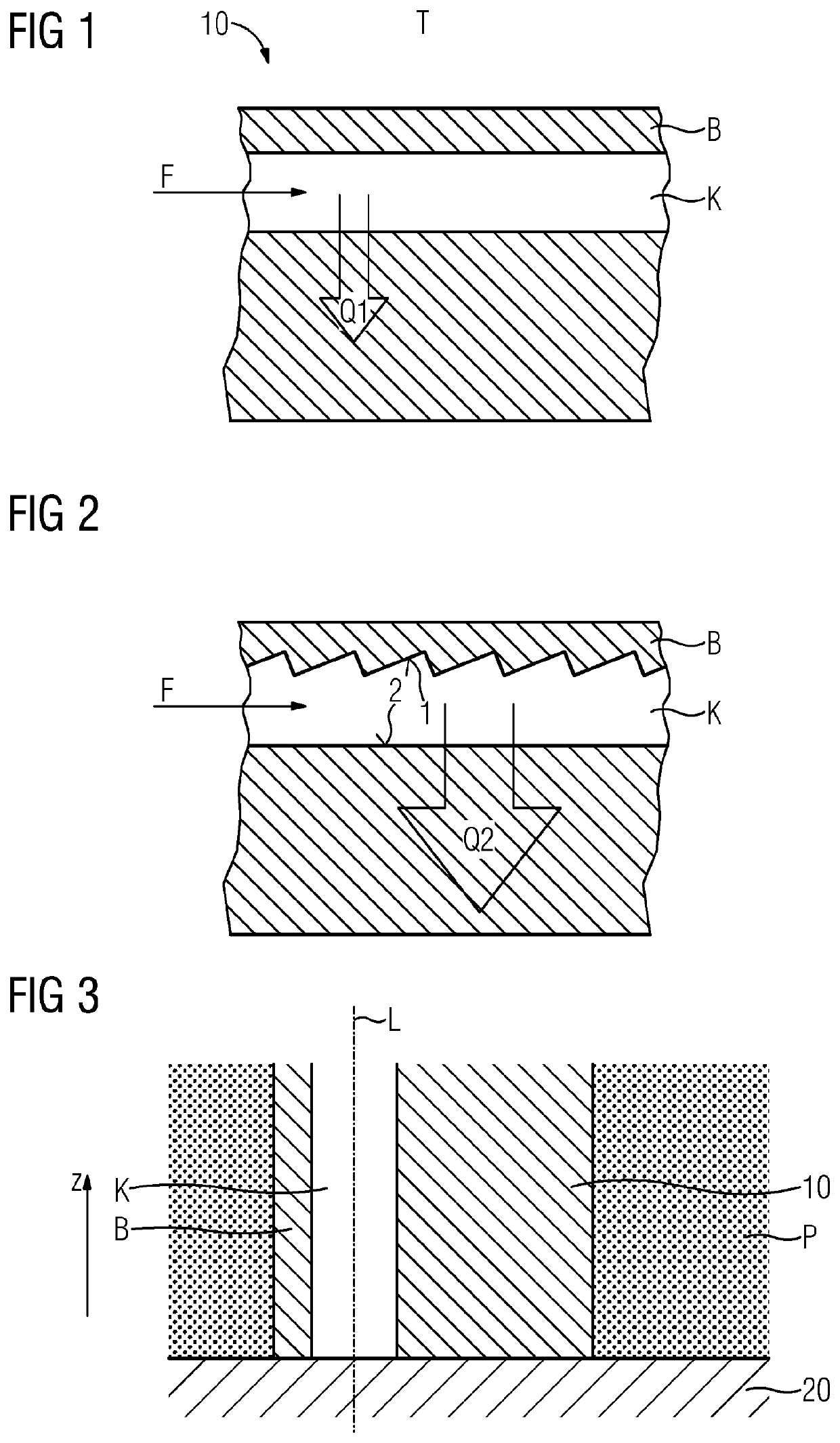
[0056]In the exemplary embodiments and figures, elements that are the same or act in the same way may be provided in each case with the same designations. The depicted elements and their sizes in relation to one another are in principle not to be regarded as true to scale; rather, individual elements may be illustrated with exaggerated thickness or size dimensions for improved clarity and / or for improved understanding.

[0057]FIG. 1 shows at least part of a component 10 in a longitudinal section. The component 10 is advantageously a component of a high-temperature-resistant material of a complicated shape to be additively manufactured from the powder bed.

[0058]The component 10 has a region B to be cooled during the operation of the same. The region B advantageously defines during the operation of the component a surrounding area by which the component is subjected to high thermal loads, such as for example a hot gas path of a gas turbine. The region B may accordingly be a wall region ...


PUM

PropertyMeasurementUnit
angleaaaaaaaaaa
angleaaaaaaaaaa
angleaaaaaaaaaa

Abstract

A component with a region to be cooled having a cooling channel which is arranged and designed so as to cool the region of the component during operation by a fluid flow, wherein the cooling channel is defined by a first channel side facing the region and by a second channel side facing away from the region. The first channel side forms a larger contact surface for the cooling channel than the second channel side. An additive manufacture process can produce the component.

Description

CROSS REFERENCE TO RELATED APPLICATIONS[0001]This application is the US National Stage of International Application No. PCT / EP2020 / 069352 filed 9 Jul. 2020, and claims the benefit thereof. The International Application claims the benefit of German Application No. DE 10 2019 214 667.8 filed 25 Sep. 2019. All of the applications are incorporated by reference herein in their entirety.FIELD OF INVENTION[0002]The present invention relates to a component that can be cooled or is to be cooled during operation, to a method for preparing for an additive manufacturing process, in particular a powder-bed-based additive manufacturing process, for the component, to a method for the additive manufacture of the component and to a use of orientation-dependent manufacturing artefacts for the forming of an advantageous surface finish of the component, in particular which allows an improved heat transmission during the operation of the component. Furthermore, a computer program or a computer program p...

Claims


Application Information

Patent Timeline
Patent Type & Authority Applications(United States)
IPC IPC(8): F01D5/18B33Y80/00B33Y10/00B22F10/28F01D25/12
CPCF01D5/187B33Y80/00B33Y10/00B22F10/28F01D25/12F05D2220/32F05D2300/175B22F5/009B22F5/04B22F10/00B33Y50/00F01D5/186F28F13/185F28F13/02F05D2260/2212F05D2250/131F05D2230/22F05D2250/121F05D2250/61F05D2250/23F05D2250/63F05D2230/31F05D2250/11F05D2230/234F05D2260/202F05D2260/201F28D2021/0026Y02P10/25
Inventor HEITMANN, TIMOALBERT, JOHANNES
Owner SIEMENS ENERGY GLOBAL GMBH & CO KG
Why Eureka
Try Eureka