Device for a satellite laser distance measurement, and method for a satellite laser distance measurement

a laser distance measurement and laser technology, applied in the direction of measurement devices, instruments, cosmonautic components, etc., can solve the problems of increasing the cost of operation, increasing the cost of construction and installation, and affecting the operation of the satellite network

Pending Publication Date: 2022-10-27
DEUTSCHES ZENTRUM FUER LUFT & RAUMFAHRT EV
View PDF0 Cites 1 Cited by
  • Summary
  • Abstract
  • Description
  • Claims
  • Application Information

AI Technical Summary

Benefits of technology

[0010]Due to the arrangement of the laser on the telescope mounting, the beam guide can be provided between the laser and the transmitter telescope, outside of the axes of rotation. By virtue of this arrangement of the laser on the telescope mounting, an expensive and complex Coudé beam guide, in which a beam guide for the laser beam must be guided through the axes of rotation of the telescope mounting, is not necessary. Thus, the size and weight of the telescope mounting as well as the overall design can be reduced significantly. The costs for such a device can be reduced considerably since a customary telescope mounting can be used.
[0041]The control software can be constructed in modules and use open source software, to the extent possible. This makes it possible for any users to expand the system themselves according to their requirements.

Problems solved by technology

However, many of the existing ILRS stations are reaching their limits with respect to the number of observed satellites.
Both the investments for construction and the installations as well as the operating costs are significant and represent a serious obstacle for expanding the network.
By virtue of this arrangement of the laser on the telescope mounting, an expensive and complex Coudé beam guide, in which a beam guide for the laser beam must be guided through the axes of rotation of the telescope mounting, is not necessary.
During the service life of a mission, it can support many position-sensitive tasks which could otherwise require difficult, bulky, and energy-intensive on-board position sensors.

Method used


Image

  • Device for a satellite laser distance measurement, and method for a satellite laser distance measurement
  • Device for a satellite laser distance measurement, and method for a satellite laser distance measurement
  • Device for a satellite laser distance measurement, and method for a satellite laser distance measurement

Examples


Embodiment Construction

[0055]Similar or equivalently-functioning components have the same reference numbers in the figures. The figures merely show examples and should not be considered restrictive.

[0056]Direction terminology used in the following with terms such as “left,”“right,”“upper,”“lower,”“in front of,”“behind,”“thereafter,” and the like are only used for better understanding of the figures and should not represent, in any case, a restriction of generality. The components and elements shown and the configuration and use thereof may vary with respect to the considerations of one skilled in the art and can be adapted to the respective applications.

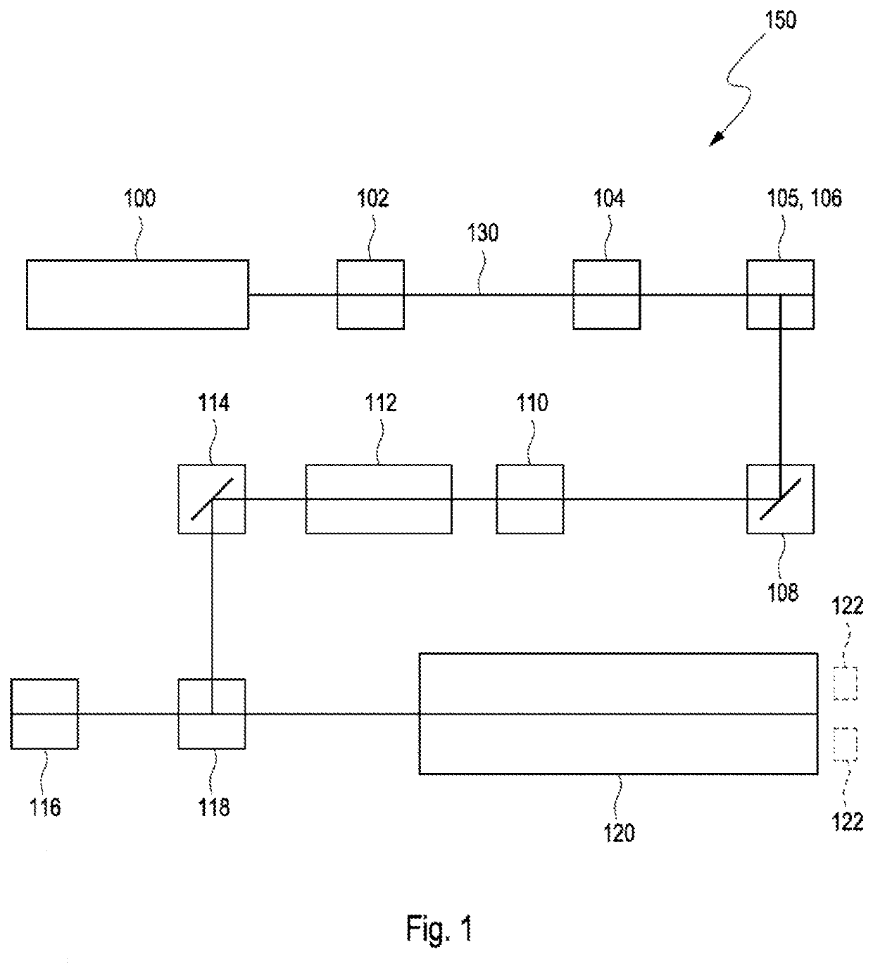
[0057]FIG. 1 shows a schematic structure of components of an optical transmitter 150 of a device 500 for satellite laser distance measurement according to an exemplary embodiment of the invention. The device may advantageously be mobile and suitable for transport on roadways.

[0058]The optical transmitter 150 consists of or comprises the laser 100 as the ac...


PUM


Abstract

A device for a satellite distance measurement includes a base segment and an optical segment which is supported by the base segment and has a telescope mounting with an azimuth axis and an elevation axis, wherein a transmitter telescope, a receiving telescope, and a laser coupled to the transmitter telescope are arranged on the telescope mounting. A method for operating such a device is also provided.

Description

BACKGROUND AND SUMMARY[0001]The invention relates to a device for satellite laser distance measurement and a method for satellite laser distance measurement.[0002]The technology of satellite laser distance measurement (SLR) has developed from a geodetic tool into a broadly used mission support instrument. There are currently about eight satellite missions relying on continuous laser distance measurement data for obtaining precise position information including several Earth-observing satellites and many navigation satellites. In yet more satellites, SLR measurements were used in the early orbit phase thereof to calibrate or to verify the on-board navigation thereof. In the future, the demand for satellite laser distance measurements could further increase since increasingly more operators of small satellites or even the proposed mega-constellations recognize the potential of this technology for obtaining orbit information, down to the centimeter, during and even after the mission. O...

Claims


Application Information

Patent Timeline
Patent Type & Authority Applications(United States)
IPC IPC(8): G01S7/481G01S17/933
CPCG01S7/4813G01S17/933G01S17/88G01S7/481B64G3/00
Inventor WAGNER, PAULDANIEL HAMPF, DANIEL HAMPF
Owner DEUTSCHES ZENTRUM FUER LUFT & RAUMFAHRT EV
Why Eureka
Try Eureka