
3-way solenoid valve, brake system for vehicle including the same, and controlling method for the same

a technology of solenoid valve and brake system, which is applied in the direction of valve housing, braking system, operating means/releasing devices, etc., can solve the problems of unsatisfactory manufacturing cost increase as well as volume and weight increase of the braking system

Pending Publication Date: 2022-11-03
HYUNDAI MOBIS CO LTD
View PDF0 Cites 1 Cited by
  • Summary
  • Abstract
  • Description
  • Claims
  • Application Information

AI Technical Summary

Benefits of technology

The present invention relates to a method for controlling a 3-way solenoid valve in a vehicle to manage fluid flow between a pressurizing device, a wheel cylinder, and an accumulator. The method involves determining the need to maintain, increase, or decrease pressure in the wheel cylinder and using the valve to regulate fluid flow between the accumulator and the wheel cylinder as well as between the wheel cylinder and the pressurizing device. The technical effect of this invention is the ability to accurately control fluid flow in a vehicle's hydraulic system, which can improve efficiency and reliability.

Problems solved by technology

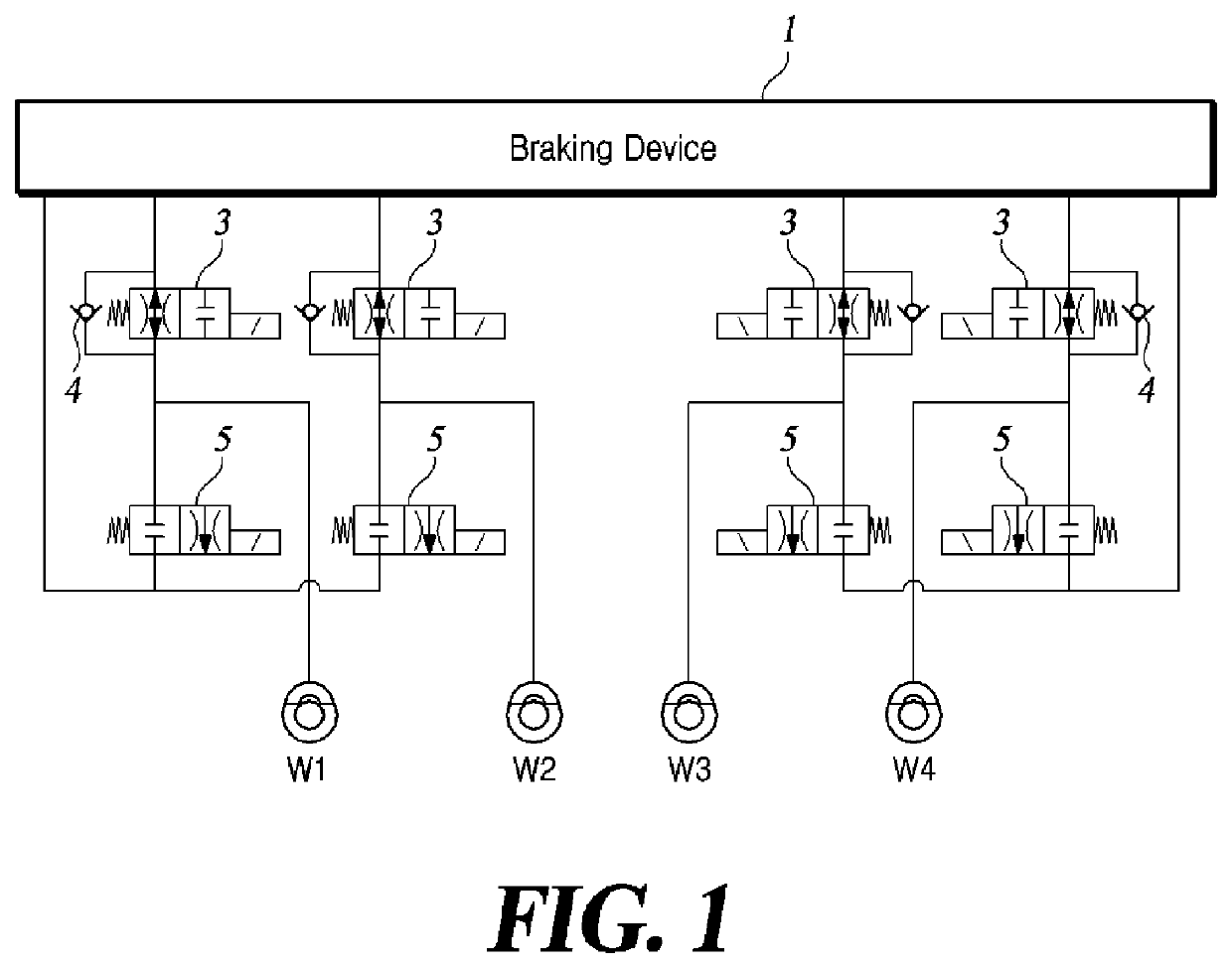
In this way, the conventional braking system for a vehicle involves too many solenoid valves of the normally open type of inlet valves 3, the normally closed type of outlet valves 5, and the check valves 4 to be installed in full, resulting in undesirable manufacturing cost increase as well as volume and weight increase of the braking system.

Method used


Image

  • 3-way solenoid valve, brake system for vehicle including the same, and controlling method for the same
  • 3-way solenoid valve, brake system for vehicle including the same, and controlling method for the same
  • 3-way solenoid valve, brake system for vehicle including the same, and controlling method for the same

Examples


first embodiment

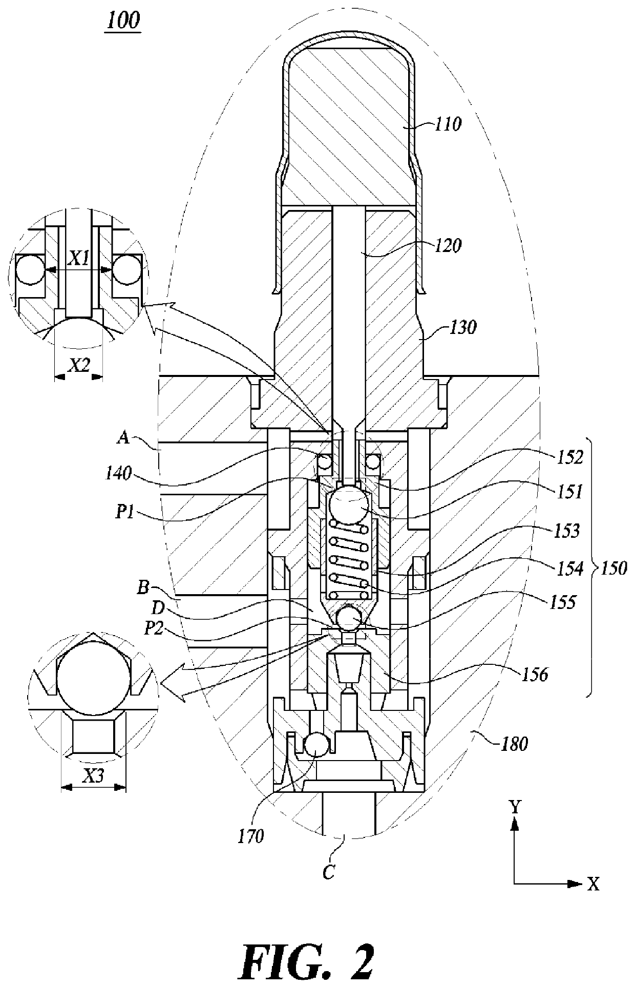
[0031]FIG. 2 is a cross-sectional view of a 3-way solenoid valve according to the present disclosure. In the present specification, the longitudinal direction of the 3-way solenoid valve is defined by the Y-axis, and the direction perpendicular to the longitudinal direction of the 3-way solenoid valve is defined by the X-axis. Among the directions shown in the drawing, an upward direction is defined as a ‘positive Y-axis’ and a downward direction is defined as a ‘negative Y-axis’.

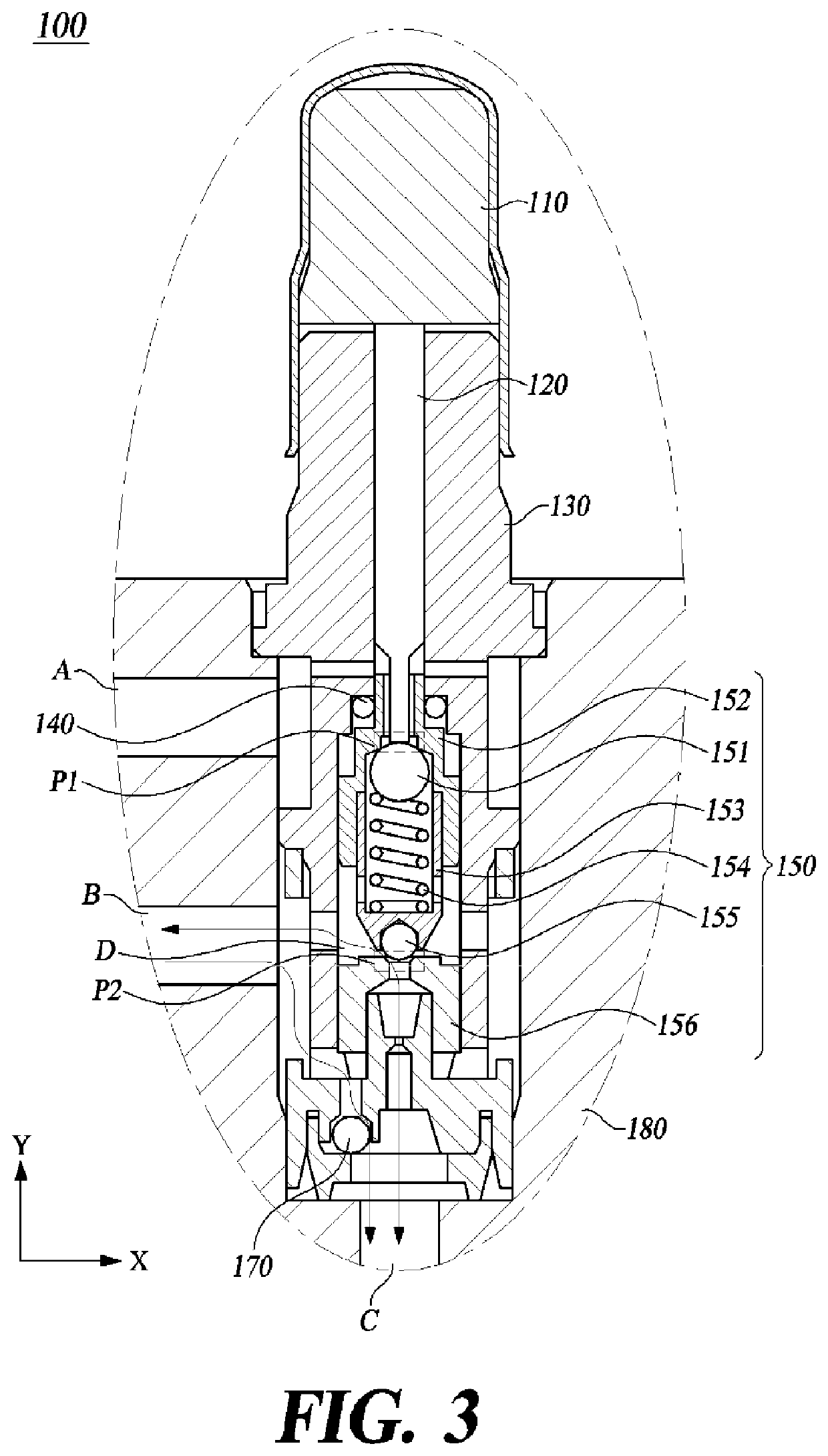
[0032]As shown in FIG. 2, the 3-way solenoid valve 100 according to the first embodiment includes all or some of an armature 110, a plunger 120, a body 130, a sealing member 140, a flow path control assembly 150, a check valve 170, and a valve block 180.

[0033]The armature 110 is configured to form an electromagnetic force in response to an electric current that is supplied. Specifically, the armature 110, which may be wrapped with a coil (not shown), forms an electromagnetic force by an electric current app...

second embodiment

[0084]FIG. 7 is a cross-sectional view of a 3-way solenoid valve 200 according to the present disclosure.

[0085]As shown in FIG. 7, the 3-way solenoid valve 200 according to the second embodiment includes all or some of an armature 110, a plunger 120, a body 130, a sealing member 140, a flow path control assembly 150, a first elastic part 154, a second elastic part 210, a check valve 170, and a valve block 180.

[0086]The 3-way solenoid valve 200 of FIG. 7 according to the second embodiment has a housing 152, 153 that is made of a housing top 152 and a housing bottom 153 which are different from the counterparts of the solenoid valve 100 of FIG. 2 according to the first embodiment. Other than that, the two 3-way solenoid valves 200 and 300 have substantially the same configuration. Therefore, a repeat description of the common parts will be omitted.

[0087]In the 3-way solenoid valve 200 according to the second embodiment, the housing bottom 153 has at its upper end a protrusion that pro...


PUM


Abstract

A 3-way solenoid valve, a vehicle brake system including the 3-way solenoid valve, and a controlling method for the same are disclosed. The present disclosure in at least one embodiment provides a brake system for a vehicle, including one or more wheel cylinders configured to apply braking pressure to each of wheels of a vehicle by using hydraulic pressure, one or more of the 3-way solenoid valve configured to increase or decrease the hydraulic pressure supplied to the one or more wheel cylinders, and a braking device configured to supply the hydraulic pressure to the one or more wheel cylinders by using a stepping force applied to a brake pedal or driving of a hydraulic pump.

Description

CROSS-REFERENCE TO RELATED APPLICATIONS[0001]This application is based on, and claims priority from, Korean Patent Application Number 10-2021-0057040, filed May 3, 2021, the disclosure of which is incorporated by reference herein in its entirety.BACKGROUND OF THE INVENTION1. Field of the Invention[0002]The present disclosure in some embodiments relates to a 3-way solenoid valve, a vehicle brake system including the 3-way solenoid valve, and a controlling method for the same.2. Discussion of Related Art[0003]The statements in this section merely provide background information related to the present disclosure and do not necessarily constitute prior art.[0004]A conventional vehicle braking system is equipped with solenoid valves of the normally open type or those of a normally closed type. The normally open type of solenoid valve has the flow path normally opened upon receiving no electric current from a control unit. Whereas, the normally closed type of solenoid valve has the flow pa...

Claims


Application Information

Patent Timeline
Patent Type & Authority Applications(United States)
IPC IPC(8): B60T15/02B60T13/68F16K11/16
CPCB60T15/028B60T13/686F16K11/161B60T13/62F16K31/0631F16K2200/301F16K2200/302B60T8/366F16K11/105F16K27/029F16K31/0624F16K31/0675F16K27/0209B60T8/3635B60T7/04B60T13/147B60Y2400/81
Inventor JEONG, SEUNG HWAN
Owner HYUNDAI MOBIS CO LTD
Learn More