

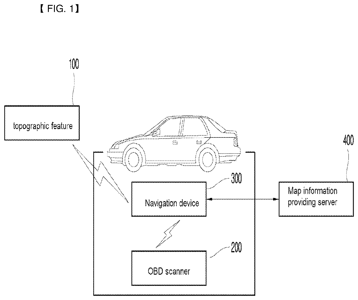
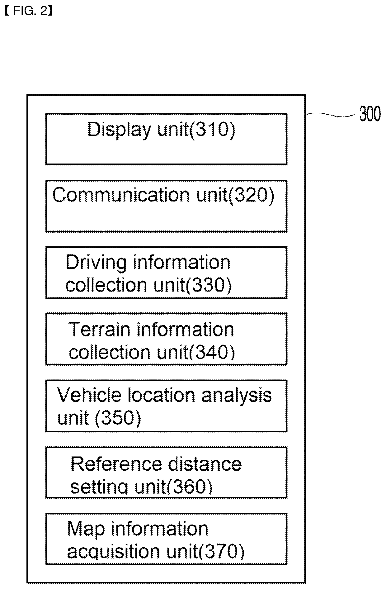
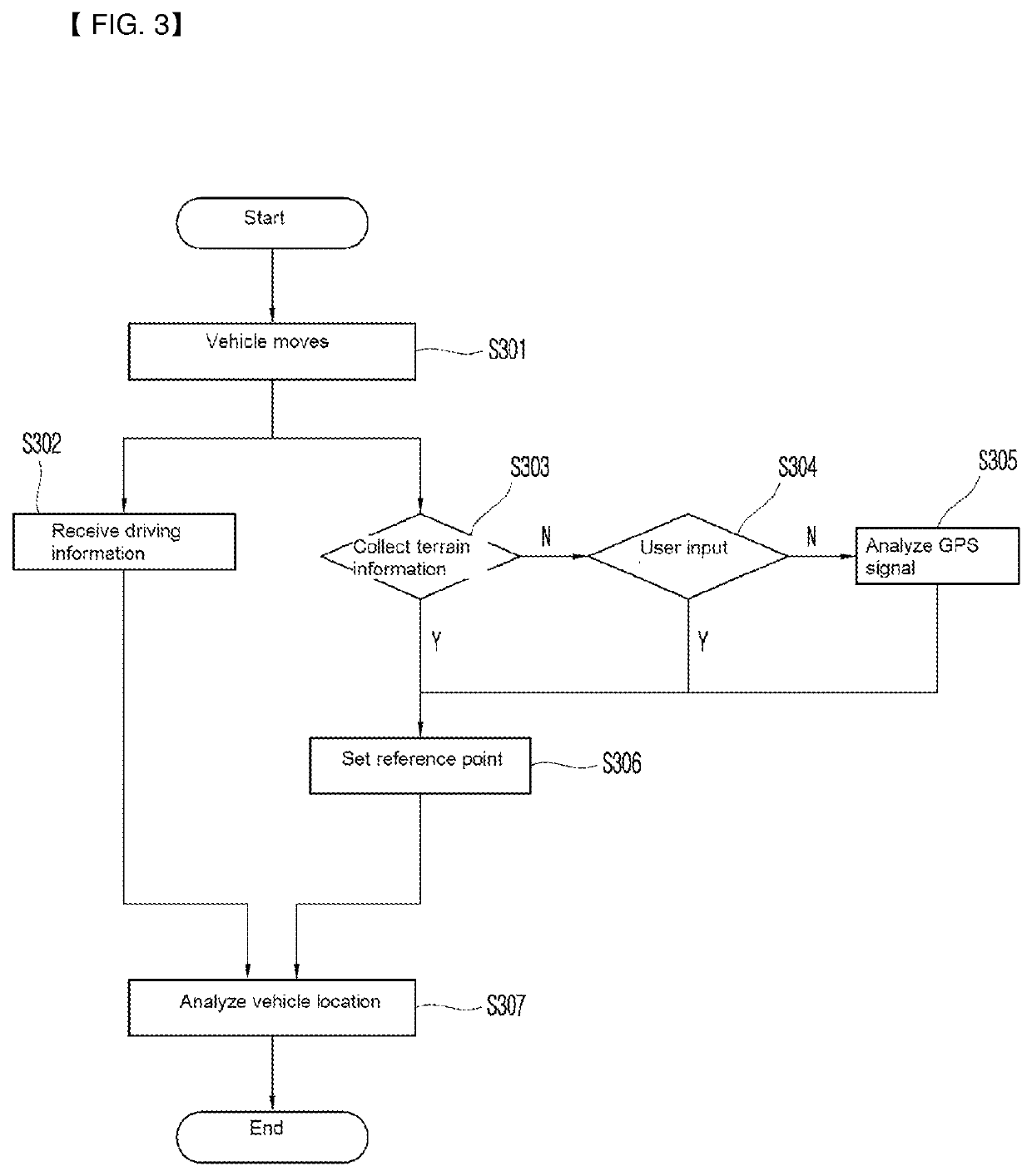
Vehicle location analysis method and navigation device
a technology of vehicle location and analysis method, which is applied in surveying and navigation, navigation instruments, instruments, etc., can solve the problems of inability to analyze the location of vehicles, undergrounds and buildings, and inability to use gps inside tunnels, etc., so as to improve the accuracy and convenience, the effect of improving the reaction speed
- Summary
- Abstract
- Description
- Claims
- Application Information
AI Technical Summary
Benefits of technology
Problems solved by technology
Method used
Image

Examples
Embodiment Construction
[0038]Hereinafter, the present invention will be described in detail with reference to the accompanying drawings. However, the present invention may be embodied in various different forms and accordingly, is not limited to the embodiments described herein. In addition, parts irrelevant to the description are omitted in the drawings to clearly describe the present invention, and like reference numerals designate like parts throughout the specification.
[0039]Throughout the specification, when a part is “connected” the other part, the above expression includes not only “being directly connected” but also “being indirectly connected” with another member interposed therebetween. In addition, when a part “includes” a certain component, the above expression does not exclude other components, but may further include the other components, unless particularly stated otherwise.
[0040]Hereinafter, the embodiments of the present invention will be described in detail with reference to the accompan...
PUM
 Abstract
Description
Claims
Application Information