
Conductive spacer for a microfluidic device

Pending Publication Date: 2022-11-10
SHARP LIFE SCI EU LTD
View PDF0 Cites 0 Cited by
  • Summary
  • Abstract
  • Description
  • Claims
  • Application Information

AI Technical Summary

Benefits of technology

This patent describes a gasket / spacer used in a microfluidic device that can provide better dispensing of droplets and enable detection of the device's manufacturing status. The gasket / spacer can have either isotropic or anisotropic conductivity. An isotropic gasket / spacer can pre-charge droplets and allows for easier dispensing, while an anisotropic gasket / spacer can enable multi-point electrical connection and top-plate resistance checking for more complex circuits. Additionally, an anisotropic gasket / spacer can carry multiple pairs of sensing signals and facilitate sensing the location and properties of droplets.

Problems solved by technology

Creating multiple top-plate vias with a simple solder paste blob may be possible for a few electrodes but quickly becomes more challenging as the number of required electrical connections to the top-plate increases.

Method used


Image

  • Conductive spacer for a microfluidic device
  • Conductive spacer for a microfluidic device
  • Conductive spacer for a microfluidic device

Examples


Embodiment Construction

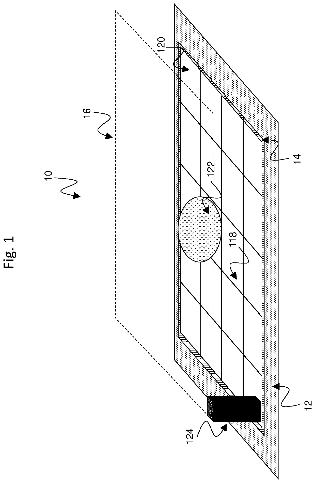
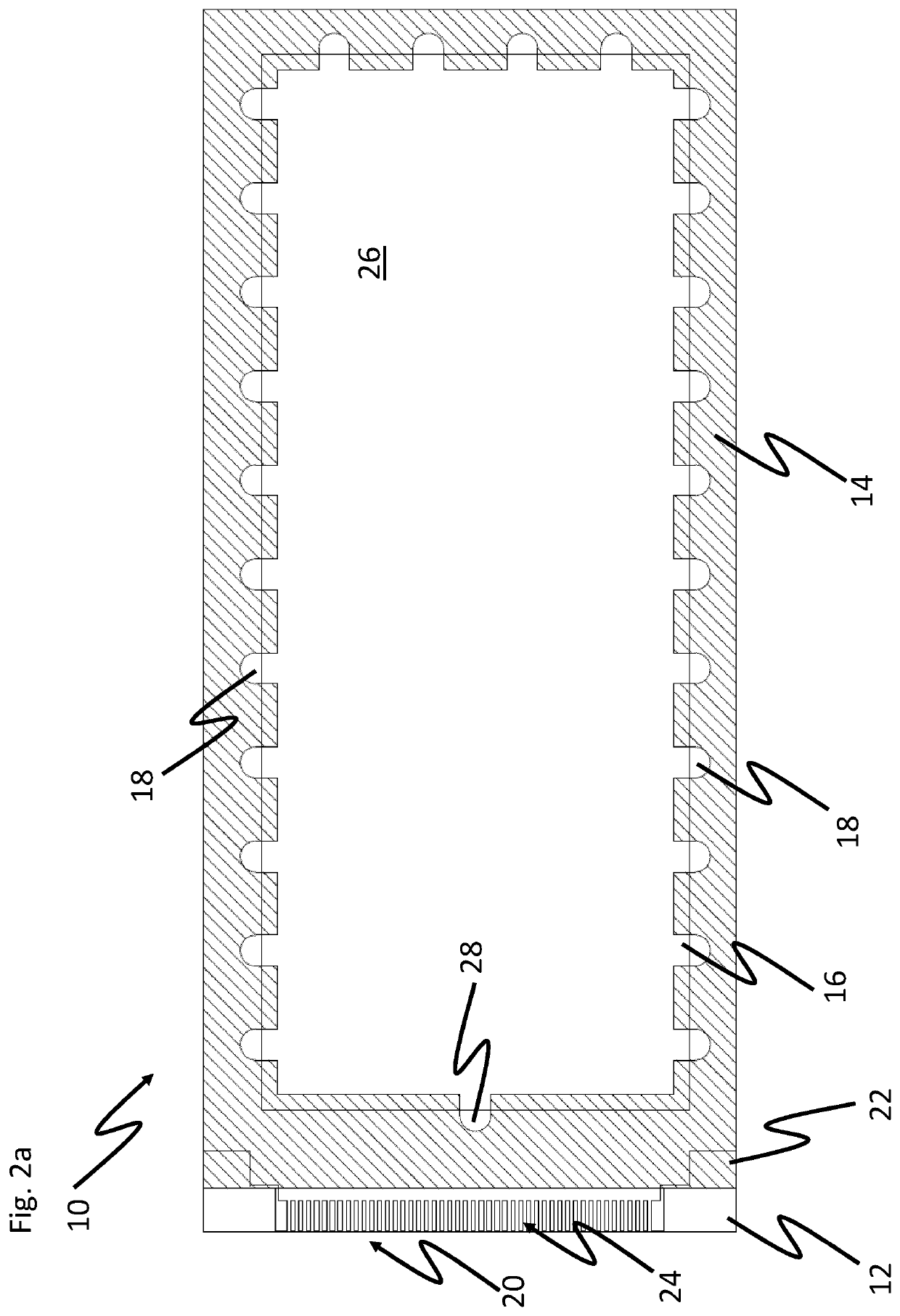
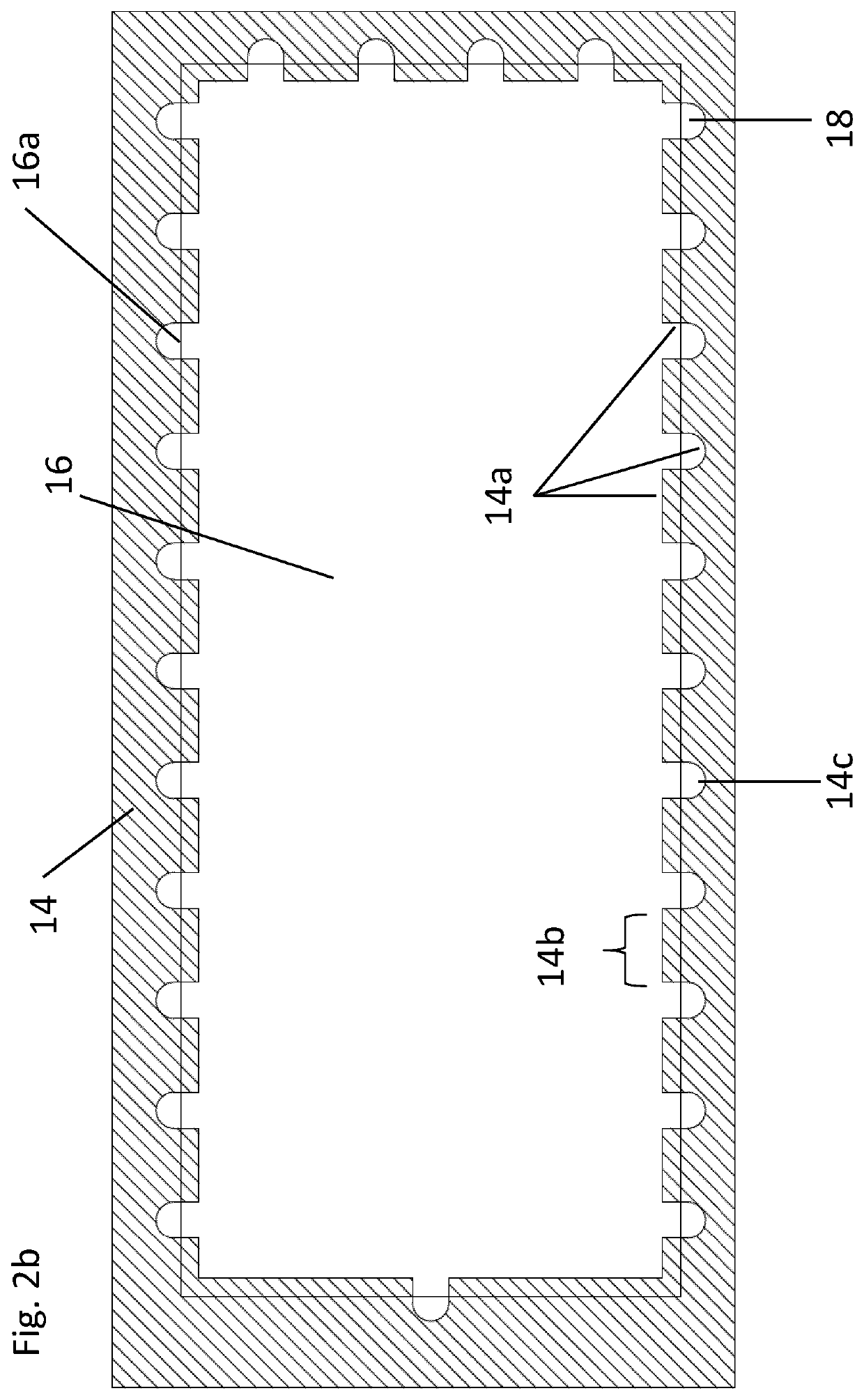
[0047]FIG. 2(a-g) represents a plan view from above of an aspect of the invention wherein an isotropic gasket is used to create a gap between the upper and lower plates of an AMEWOD device.

[0048]FIG. 2a shows a plan view from above of an exemplary AMEWOD device (10) according to an aspect of the invention, where a liquid sample is introduced to the device along an edge of an upper substrate. AMEWOD device (10) comprises a lower substrate (12), a gasket (14), upper substrate (16), port (18, 28), edge connector (20) and contact pad (22). For clarity, FIG. 2b shows the gasket (14) and upper substrate (16) only, and FIG. 2c shows the lower substrate only. Line 23 in FIG. 2c denotes the boundary of the active area of the device.

[0049]The fluid chamber of the EWOD device corresponds to the aperture or bore in the interior of the gasket. The boundaries of the fluid chamber are defined by the lower substrate, the upper substrate, and the inner edge face of the gasket.

[0050]Edge connector (2...


PUM

PropertyMeasurementUnit
conductiveaaaaaaaaaa
thicknessaaaaaaaaaa
electrically conductiveaaaaaaaaaa

Abstract

A microfluidic device comprises a first substrate and a second substrate, a gasket spacing the first substrate from the second substrate to define a fluid chamber between the first substrate and the second substrate, and at least one port for introducing a fluid sample into the fluid chamber. An inner edge face of the gasket defines a lateral boundary of the fluid chamber. A plurality of independently addressable array elements are provided on a surface of the first substrate facing the fluid chamber, and at least one circuit element is disposed on a surface of the second substrate facing the fluid chamber. The gasket is configured to provide a conductive path between a circuit element disposed on a surface of the second substrate facing the fluid chamber and an associated terminal.

Description

TECHNICAL FIELD[0001]The present invention relates to a microfluidic device and a method of using such a device. Aspects of the invention relate to pre-charging a droplet of fluid either as it is transferred into the microfluidic device or at some point after it is transferred into the microfluidic device. Further aspects of the invention relate to conductive circuits for interrogating the property of one or more droplets within the microfluidic device.BACKGROUND ART[0002]Co-pending European patent applications of the applicant, Nos. 18182737.9, 18182772.6, 18194096.6, and 18194098.2, disclose aspects of a microfluidic system, including a side-fill configuration and a moulded housing for a microfluidic element, the contents of which are incorporated herein by reference.[0003]U.S. Pat. No. 9,019,200 discloses a method for driving an electro-wetting display panel and electro-wetting display apparatus for performing the same.[0004]Choi, K., Im, M., Choi, J M. et al. Microfluid Nanoflui...

Claims


Application Information

Patent Timeline
Patent Type & Authority Applications(United States)
IPC IPC(8): B01L3/00
CPCB01L3/502784B01L3/50273B01L2300/0645B01L2400/0427B01L2300/0861B01L2200/12B01L2300/089B01L2300/0816B01L2200/0673B01L2200/026B01L2200/0689
Inventor PARRY-JONES, LESLEY ANNEWALTON, EMMA JAYNEBROWN, CHRISTOPHER JAMES
Owner SHARP LIFE SCI EU LTD
Learn More