Aerosol valve with defined flow paths

a technology of flow path and valve body, which is applied in the direction of liquid handling, instruments, volume metering, etc., can solve the problems of clogging flow path, affecting product formulations, and affecting the product formulation structure, so as to reduce back pressure and maximize product impingement

Inactive Publication Date: 2016-01-14
PRECISION VALVE CORP
View PDF22 Cites 1 Cited by
  • Summary
  • Abstract
  • Description
  • Claims
  • Application Information

AI Technical Summary

Benefits of technology

[0007]The present disclosure provides an aerosol valve that provides an additional flow path for the product and propellant that improves mixing of the product formulation.
[0008]The present disclosure also provides such an aerosol valve that provides an additional flow path for the product and propellant that improves mixing of the product formulation, reduces agglomeration of solids in the product that might otherwise clog the flow paths in the aerosol valve, increases turbulence of the product formulation as it flows through the aerosol valve, and feeds more of the product directly to the aperture for better dispensing of the product.
[0009]The present disclosure further provides an aerosol valve having a valve stem, housing, compression spring, and a hard stop between the valve stem and housing. The hard stop prevents the compression spring from becoming fully-compressed (coil-bound) when the consumer presses on the valve stem to dispense a product, so that there are open spaces between adjacent coils of the compression spring.
[0011]The present disclosure also provides that the compression spring has these open spaces that can function as a baffle and a static mixer for the product formulation to improve the mixing of the solids in the product formulation as they flow through the aerosol valve.
[0012]The present disclosure further provides that the spaces between the coils of the compression spring also increase turbulence in the flow path, and can break up agglomerations of solids in the product formulation that might otherwise clog the flow path.
[0015]The present disclosure also provides that the aerosol valve has a valve stem with large cross-section passageways that allow the product formulation to flow directly from the dip-tube through the center of the compression spring. This configuration allows the product flow to be gently deflected around the valve stem, which reduces back pressure (resistance).

Problems solved by technology

Aerosol valve structures for product formulations that contain solids can fail because of agglomeration (clumping) of solids in the flow passages in the internal space of the valve stem housing.
Conventional designs of aerosol valves often employ flow paths that have long, narrow channels, abrupt changes in flow direction, and areas of recirculation—any or all of which can cause solids in the product formulation to clump and clog the flow paths.
However, the compressed spring coils form a barrier to the product formulation that is flowing upward, and so forces the product and propellant to follow a flow path that is nearly entirely along the outside of the fully-compressed spring coils, since there is little or no space between the spring coils to permit the product formulation and propellant to flow in between the spring coils or access the volume in the center of the compression spring.

Method used


Image

  • Aerosol valve with defined flow paths
  • Aerosol valve with defined flow paths
  • Aerosol valve with defined flow paths

Examples


Embodiment Construction

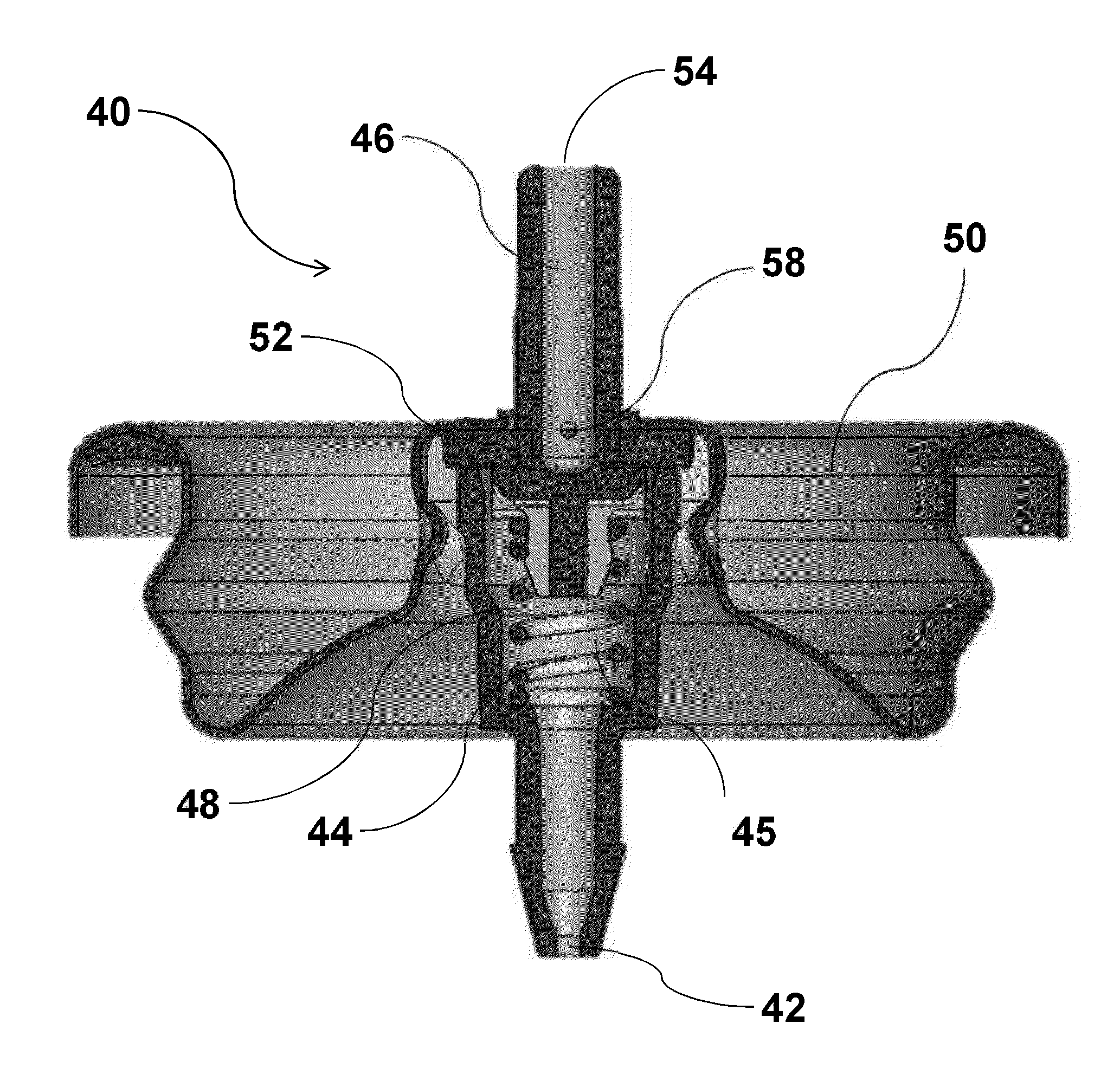
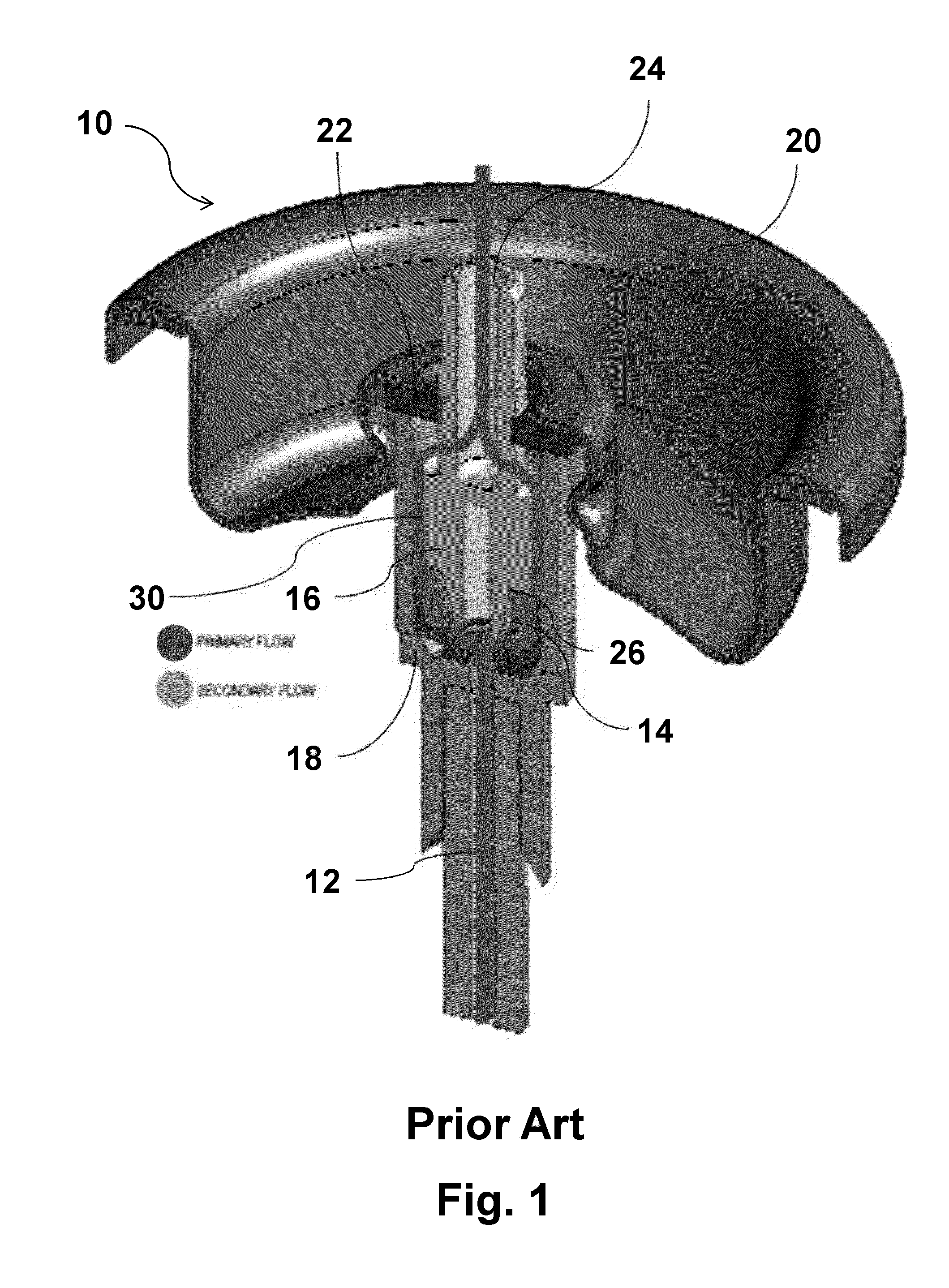
[0034]Referring to the drawings and, in particular, FIG. 1 that is a conventional or prior art aerosol valve generally represented by reference numeral 10. Valve 10, shown in FIG. 1 in full stroke, shows the flow path of the product formulation around the outside of the compression spring before the formulation is able to enter the center hole (aperture) of the valve stem.

[0035]Aerosol valve 10 includes a dip tube 12, compression spring 14, valve stem 16, valve stem housing 18, mounting cup 20, and seal 22. Valve stem 16 is enclosed in valve stem housing 18. Valve stem 16 has a pair of apertures (not shown in FIG. 1) through which a pressurized high-solids product formulation passes in order to enter center hole 24 of valve stem 16. Mounting cup 20 orients and stabilizes aerosol valve 10 in its proper position on the product. Valve stem 16 contacts compression spring 14 at contact point 26.

[0036]Compression spring 14 exerts an upward pressure on valve stem housing 18, which is press...


PUM


Abstract

An aerosol valve having a valve stem, valve stem housing, compression spring, and a hard stop formed by the interaction of valve stem and valve stem housing is provided. The hard stop prevents the compression spring from becoming fully compressed, or coil-bound, when the valve stem is pressed to dispense a product formulation from the container, thereby creating open spaces between coils of the compression spring and providing a defined flow path for the product formulation. The aerosol valve increases mixing and turbulence of the product formulation that reduce agglomerations of solids that might otherwise block the flow paths. The additional defined flow path also directs more of the product to the valve stem aperture, further increasing dispensing of the product formulation from the container. A method of using the aerosol valve is provided.

Description

BACKGROUND OF THE DISCLOSURE[0001]1. Field of the Disclosure[0002]The present disclosure relates to the field of aerosol valves for delivery of product formulations having solids. More particularly, the present disclosure relates to an aerosol valve having a valve stem, compression spring, and a hard stop that prevents full compression of the compression spring when the valve stem is pressed by the consumer to dispense the product formulations having solids, creating defined flow paths.[0003]2. Description of Related Art[0004]Aerosol valve structures for product formulations that contain solids can fail because of agglomeration (clumping) of solids in the flow passages in the internal space of the valve stem housing. Conventional designs of aerosol valves often employ flow paths that have long, narrow channels, abrupt changes in flow direction, and areas of recirculation—any or all of which can cause solids in the product formulation to clump and clog the flow paths.[0005]Also, conv...

Claims


Application Information

Patent Timeline
Patent Type & Authority Applications(United States)
IPC IPC(8): B65D83/48B65D83/32
CPCB65D83/32B65D83/48B05B7/0483B65D83/34B65D83/46
Inventor FORE, JOHN B.DOWNEY, MICHAEL PAULBRACE, GEOFFREY
Owner PRECISION VALVE CORP
Why Eureka
Try Eureka