
Hybrid propulsion architecture and aircraft containing such an architecture

Pending Publication Date: 2022-11-10
SAFRAN
View PDF0 Cites 0 Cited by
  • Summary
  • Abstract
  • Description
  • Claims
  • Application Information

AI Technical Summary

Benefits of technology

The invention aims to simplify and decrease the cost of a hybrid propulsion architecture by creating common points through which electrical energy can flow from a single first source of a first type of energy towards different charges, while ensuring non-propagation of defects on the charges through these common points. This reduces the number of energy sources needed and increases reliability, reducing cost and mass of the architecture. The invention also allows the plurality of propulsion channels to be powered simultaneously, ensuring no single failure can generate the loss of more than one propulsion channel.

Problems solved by technology

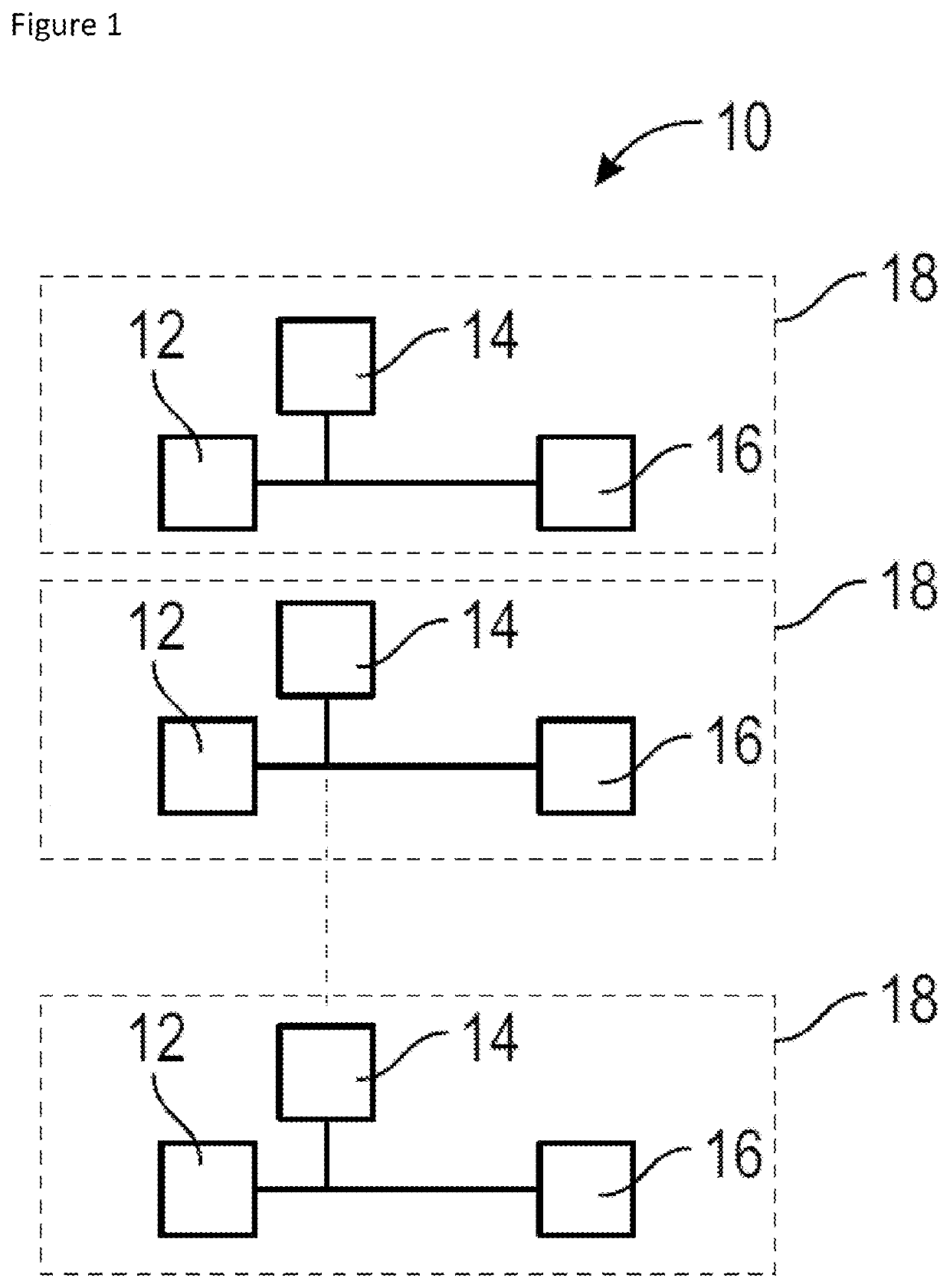
However, this architecture is costly, since it integrates a large number of sources.
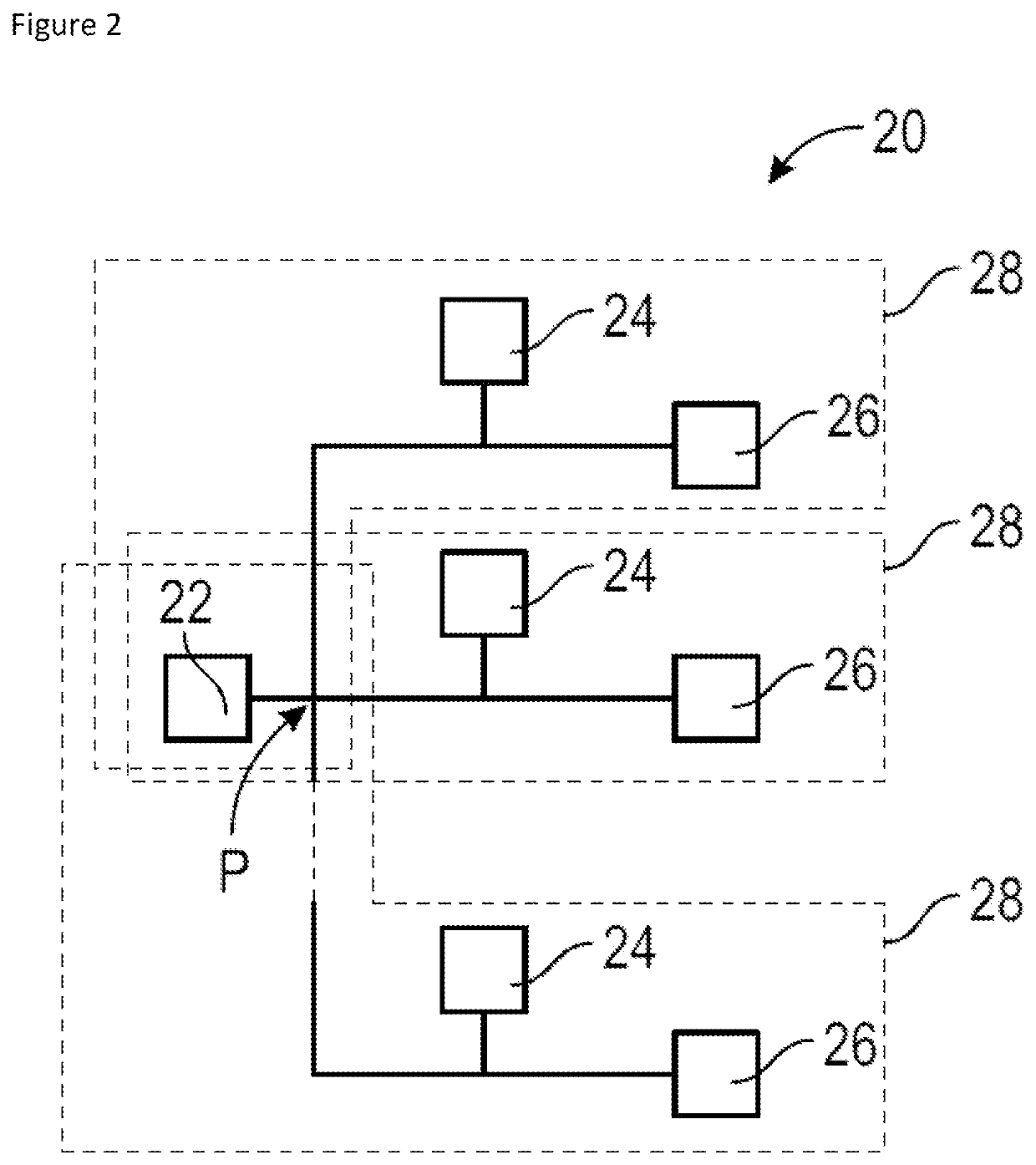
However, in such an architecture, there is a common point P between the different propulsion channels, which can propagate a fault from one propulsion channel to another propulsion channel, and thus generate the loss of several propulsion channels following a single failure.
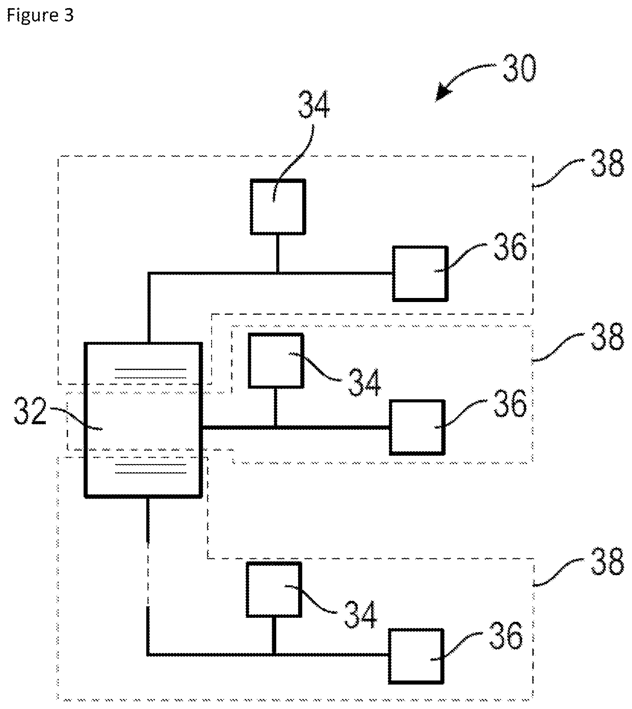
However, in this architecture, the design of the first source is constrained, both in terms of cost and complexity.
In addition, the technological solutions allowing to realise a decoupling of the propulsion channels within the first source are currently poorly mastered, and some modes of malfunction are not resolved.
However, the design of such an alternator does not allow for independence of the outputs, especially in the event of a fault.
In addition, this architecture lacks flexibility in the power distribution.
Thus, the electrical system is unable to provide more than 100 kW of power to a propulsion channel, even if the total consumption of the electrical system is less than 300 kW.

Method used


Image

  • Hybrid propulsion architecture and aircraft containing such an architecture
  • Hybrid propulsion architecture and aircraft containing such an architecture
  • Hybrid propulsion architecture and aircraft containing such an architecture

Examples


Embodiment Construction

[0058]FIGS. 4 to 8 show a hybrid propulsion architecture 100 according to the invention, for a VTOL aircraft, such as a dual-rotor counter-rotating quadricopter.

[0059]The architecture 100 comprises a single first source 102 of a first type of energy. For example, as shown in FIGS. 5 to 8, the first source 102 comprises a gas turbine 110 and a variable frequency generator 112, followed by a passive rectifier 114. The rectifier 114 is an AC-DC converter.

[0060]The first source 102 may also be a battery, for example a lithium-ion battery. Thus, the first source 102 may be an electrical-thermal generation source, or an electrochemical storage source.

[0061]The architecture 100 comprises second sources 104 of a second type of energy, which is different from the first type of energy of the first source 102. In FIG. 4, three second sources 104 are shown, and in FIGS. 5 to 8, four second sources 104 are shown.

[0062]For example, the second sources 104 may comprise permanent magnet generators. ...


PUM


Abstract

The invention relates to a hybrid propulsion architecture (100) for an aircraft, comprising: —a first source (102) of a first energy type, —second sources (104) of a second energy type different from the first energy type, —electrical propulsion systems (106), —an electric power supply network (118) connecting the first and second sources (102, 104) to the electrical propulsion systems, such that each electrical propulsion system is powered by the first source and by one of the second sources, the architecture being characterised in that it further comprises: —means for segregating (120) the electrical propulsion systems, which means are arranged in the electric power supply network and configured to impose a direction of flow of the electric power from the first source to the electrical propulsion systems.

Description

TECHNICAL FIELD[0001]The invention concerns a hybrid propulsion architecture and a multi-rotor vertical take-off and landing (VTOL) aircraft, such as a dual-rotor counter-rotating quadricopter, comprising such a hybrid propulsion architecture.PRIOR ART[0002]The prior art comprises, in particular, the documents FR-A1-3 079 210, EP-A2-2 040 370 and US-A1-2016 / 016670. The document FR-A1-3 079 210 describes a hybrid propulsion architecture that comprises a first source of a first type of energy, second sources of a second type of energy, electrical propulsion systems and an electrical energy supply network that connects the assembly.[0003]In a known way, a hybrid propulsion architecture is an architecture which uses several energy sources of different type, for example electric-thermal and electrochemical, to feed propulsion systems, and therefore which uses several energy sources of different type for each propulsion channel.[0004]A hybrid propulsion architecture is known, in which the...

Claims


Application Information

Patent Timeline
IPC IPC(8): B64D27/24B64C29/00
CPCB64D27/24B64C29/0008B64D2027/026B64D27/02B64D35/02H02J1/108H02J2310/44H02J1/106H02J1/102H02J7/342H02J7/1423H02J7/1438Y02T50/60B64D27/026H02J1/10
Inventor BIAUJAUD, REMYMEUNIER, RENEMORA, JEROME DIDIERROUGIER, MOISSY-CRAMAYELVALIRE, JEROME
Owner SAFRAN
Learn More