Micromechanical inertial sensor

a micromechanical and sensor technology, applied in the direction of acceleration measurement in multiple dimensions, acceleration measurement using interia forces, instruments, etc., to achieve the effects of high mechanical vibration, reliable recognition of signal errors, and increased safety of the overall system

Pending Publication Date: 2022-11-10
ROBERT BOSCH GMBH
View PDF3 Cites 0 Cited by
  • Summary
  • Abstract
  • Description
  • Claims
  • Application Information

AI Technical Summary

Benefits of technology

[0013]Interference accelerations above the useful band of the low-g sensor may be measured with the aid of the micromechanical inertial sensor according to the present invention. Advantageously, the measurement of the high-g sensor may be used to compensate for and reliably recognize signal errors, which occur in the signal of the low-g sensor, of signals within its measuring range, if the interference acceleration in the surroundings moves the low-g sensor outside the mechanical or electrical measuring range, and thus it is not possible to carry out a reliable measurement. In addition to monitoring the interference acceleration at the installation location, the low-g acceleration sensor may also be continuously monitored or subjected to a plausibility check by the high-g sensor and, if necessary, may recognize spontaneously occurring hardware defects. In this way, the safety of the overall system is increased. Moreover, mechanical changes on the vehicle which result in high mechanical vibrations or another misuse case may be recognized. The signals of the high-g sensor could, for example in a motorcycle, also be used for recognizing and evaluating an accident situation (eCall). The high-g signals are additionally available for further applications in the control unit.
[0014]Additionally, mechanical defects may be detected in the application at the motor vehicle or motorcycle, which generate high interference accelerations, such as, for example, an engine or transmission damage or an installation of problematic mechanical additional components. In particular, such randomly occurring defects in the application are very difficult to take into consideration during the development process. Here, the present invention enhances the safety of the overall system and simplifies the release process since the vibration surroundings are continuously monitored by the high-g sensor.
[0015]During the release process of the motor vehicle control units, the high-g sensors may additionally save costs since a complex installation of external reference sensors may be dispensed with in many cases, and the high-g data may be utilized directly here. In addition, a possible misuse of the sensor due to incorrect installation may be detected.

Problems solved by technology

One problem that may occur with almost all applications are external vibration interferences which occur outside the sensor useful band.
This may result in various undesirable sensor errors.
For example, offset errors may occur in the signal, or the sensor element may be moved into the mechanical fixed stop and thus cannot carry out a reliable measurement of the linear acceleration or rotation rate.
These states cannot always be detected by the sensor itself.
This is a very time-consuming and costly process.
If defects occur at the installation location of the sensor which cause high vibration signals, such as, for example, engine or transmission damage, they can be examined only poorly, or not at all, during the development phase.
Advantageously, the measurement of the high-g sensor may be used to compensate for and reliably recognize signal errors, which occur in the signal of the low-g sensor, of signals within its measuring range, if the interference acceleration in the surroundings moves the low-g sensor outside the mechanical or electrical measuring range, and thus it is not possible to carry out a reliable measurement.
In addition to monitoring the interference acceleration at the installation location, the low-g acceleration sensor may also be continuously monitored or subjected to a plausibility check by the high-g sensor and, if necessary, may recognize spontaneously occurring hardware defects.
Additionally, mechanical defects may be detected in the application at the motor vehicle or motorcycle, which generate high interference accelerations, such as, for example, an engine or transmission damage or an installation of problematic mechanical additional components.
In particular, such randomly occurring defects in the application are very difficult to take into consideration during the development process.
During the release process of the motor vehicle control units, the high-g sensors may additionally save costs since a complex installation of external reference sensors may be dispensed with in many cases, and the high-g data may be utilized directly here.
In addition, a possible misuse of the sensor due to incorrect installation may be detected.

Method used


Image

  • Micromechanical inertial sensor
  • Micromechanical inertial sensor

Examples


Embodiment Construction

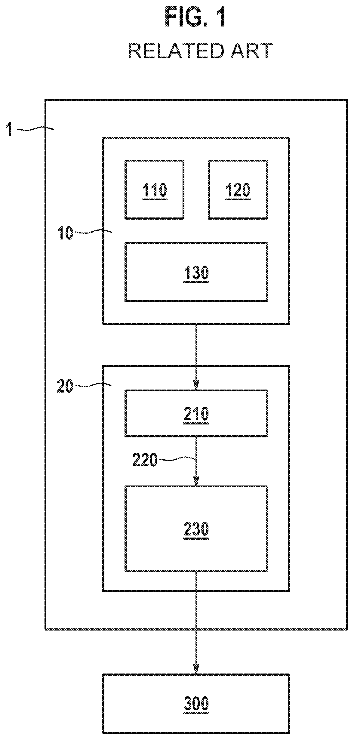
[0019]FIG. 1 schematically shows a low-g acceleration sensor in the related art. An inertial sensor 1 is illustrated, here a three-channel low-g acceleration sensor including a MEMS chip 10 and an ASIC 20. First capacitive sensor elements 110, 120, 130 for low-g acceleration measurement in the spatial directions x, y, z are integrated on the MEMS chip. A first capacitance-to-voltage converter (C / V converter) 210 for generating a voltage corresponding to the present acceleration per channel is integrated on ASIC 20, which supplies a first measuring signal 220. Furthermore, a first signal processor 230 for signal processing is integrated, which is configured to output a low-g acceleration signal 300.

[0020]These sensors typically have bandwidths of 50 Hz to 400 Hz. The bandwidth is reduced by the ASIC to the desired degree to keep the noise of the sensor as low as possible. The typical bandwidth of the MEMS sensor element is 3 kHz to 5 kHz. In a range of 400 Hz to several kHz, it is th...


PUM


Abstract

A micromechanical inertial sensor. The inertial sensor includes a first sensor element for measuring an inertial variable in a first frequency band, and a second sensor element for measuring a periodic acceleration in a second frequency band. The second frequency band is at least partially above the first frequency band.

Description

FIELD[0001]The present invention is directed to a micromechanical inertial sensor including a first sensor element for measuring an inertial variable in a first frequency band.BACKGROUND INFORMATION[0002]MEMS inertial sensors (rotation rate and acceleration sensors) have been well-established in many safety applications in the motor vehicle for quite some time and have meanwhile also found their way into many everyday products, such as smart phones.[0003]One problem that may occur with almost all applications are external vibration interferences which occur outside the sensor useful band. This may result in various undesirable sensor errors. For example, offset errors may occur in the signal, or the sensor element may be moved into the mechanical fixed stop and thus cannot carry out a reliable measurement of the linear acceleration or rotation rate. These states cannot always be detected by the sensor itself. The useful band of the sensor, also limited by the data processing in the ...

Claims


Application Information

Patent Timeline
Patent Type & Authority Applications(United States)
IPC IPC(8): G01P15/08G01P15/125
CPCG01P15/0888G01P15/125G01P3/00G01P15/02G01P15/18G01C19/5776
Inventor PETZOLD, KLAUSWOLPERT, REINHOLDGUENTHER, SEBASTIANSZKUPIEN, ZOLTAN
Owner ROBERT BOSCH GMBH
Why Eureka
Try Eureka