
Diagnostic and control method for a vehicle system

a vehicle system and diagnostic method technology, applied in the direction of program control, testing/monitoring control system, instruments, etc., can solve the problems of unintended behavior, unintended behavior, unintended acceleration changes, etc., to achieve efficient diagnostic routine execution, simple and reliable system, and higher accuracy

Active Publication Date: 2022-11-17
DANA BELGIUM
View PDF5 Cites 0 Cited by
  • Summary
  • Abstract
  • Description
  • Claims
  • Application Information

AI Technical Summary

Benefits of technology

The patent text describes a method for operating a vehicle system to detect and prevent faults that could cause unexpected acceleration or handling performance issues. The method involves monitoring the input device state and the electric machine torque, and detecting a fault condition based on these inputs. When a fault is detected, the system can trigger a fault state and control the vehicle component in a safe manner to prevent unintended acceleration or changes in vehicle performance. This method provides a simple and reliable solution to prevent faults and enhance operator's perception of vehicle handling performance.

Problems solved by technology

Different sets of vehicle driveline conditions may lead to unintended behaviors.
The unintended behaviors may include unwanted changes in vehicle acceleration and other undesirable kinematic behavior.
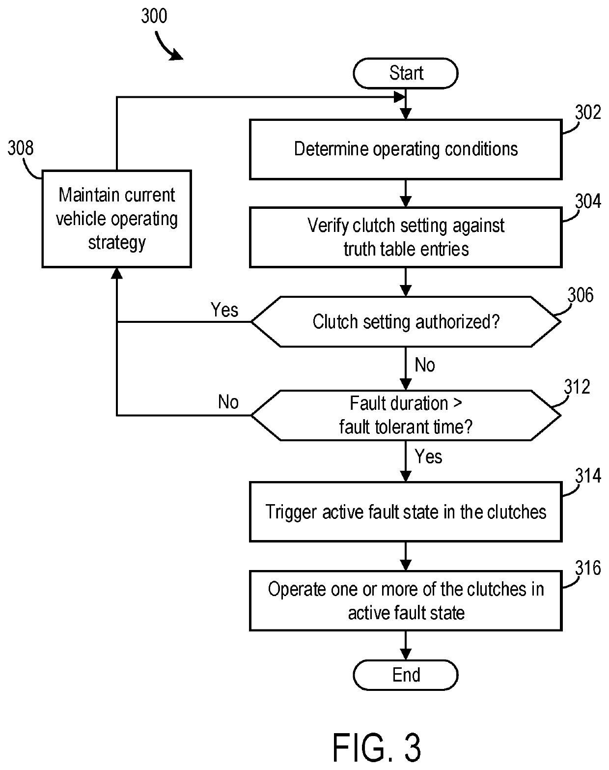
For instance, a number of conditions can cause erroneous clutch settings that may lead to unwanted vehicle braking or movement in an unintended direction.
For instance, fault detection strategies which rely on comparison of actual vs. intended gear ratio are processing intensive strategies that may lead to the incorrect identification of a fault, in certain situations.
This superfluous fault detection may restrict vehicle performance and lead to unnecessary servicing of the vehicle, in some cases.
This may involve complex processing strategies that are not always effective or reliable, due to the fault misdiagnoses, described above.
Additionally, using a single controller for both diagnostic and control operations may prove to be inflexible and inefficient with regard to altering or updating routines of either operation.
Further, other prior fault detection strategies have involved complex systems that use a comparatively large number of inputs and guard against a large number of unwanted settings such as software faults, hydraulic faults, etc.
As such, previous diagnostic strategies may demand a large amount of processing resources to implement, and therefore may decrease the system's processing efficiency.
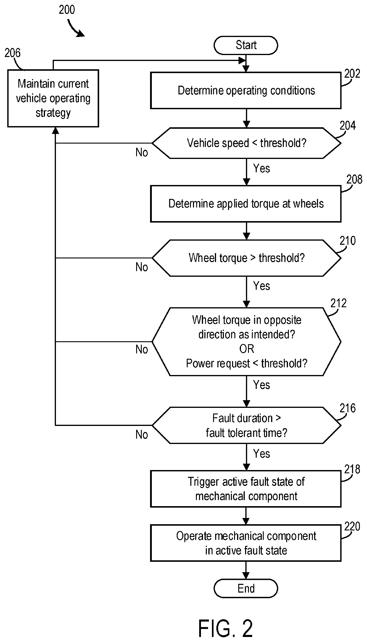
In one example, a method is provided to identify a condition where excessive drive torque is anticipated to be applied to the vehicle wheels in the case of no or low throttle demand, which may result in unintended longitudinal vehicle acceleration.
Further, the diagnostic controller may inhibit the determination of a fault condition when the vehicle speed exceeds a threshold value, since at higher speeds, the torque exceeding the threshold torque may lead to a proportionally small amount of vehicle acceleration.
In other words, at higher vehicle speeds, a vehicle operator may not perceive a smaller but unintended increase in vehicle speed due to the unintended clutch and / or electric machine settings, for example, and triggering a fault under these conditions may therefore be foregone.

Method used


Image

  • Diagnostic and control method for a vehicle system
  • Diagnostic and control method for a vehicle system
  • Diagnostic and control method for a vehicle system

Examples


Embodiment Construction

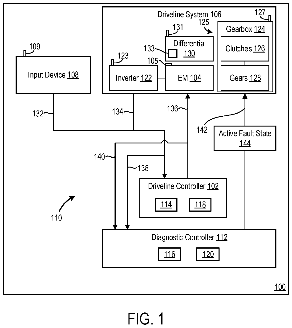
[0016]The following description relates to a driveline component control strategies and fault diagnostics in a vehicle system. The system uses efficient logic for confident and independent fault diagnosis to reduce the likelihood of undesired driveline and more generally vehicle behaviors. The system uses independent controllers, or processing units, to implement nominal driveline control strategies and diagnostic (e.g., fault detection) strategies. As such, diagnostic routines may be executed independently from nominal control strategies and is not influenced by the nominal control strategies. Thus, a diagnostic controller determines a fault condition of a driveline component and triggers a fault state to operate the driveline component in a fault mode, overriding the nominal control settings of a driveline controller. The separation of control and diagnostic logic allows for independent alteration of control and fault applications, providing increased system adaptability and diagn...


PUM


Abstract

Methods and systems are provided for controlling and diagnosing a mechanical vehicle component. In one example, a method may include determining an input device state and an electric machine torque at a diagnostic controller, and identifying a fault condition based on these determinations. Further, the diagnostic controller may trigger an active fault state of the mechanical vehicle component to avoid unintended vehicle acceleration, particularly at low speeds.

Description

TECHNICAL FIELD[0001]The present description relates generally to control and diagnostic strategies in a vehicle system. More particularly, the present description relates to techniques for fault monitoring in a driveline system.BACKGROUND AND SUMMARY[0002]Different sets of vehicle driveline conditions may lead to unintended behaviors. The unintended behaviors may include unwanted changes in vehicle acceleration and other undesirable kinematic behavior. For instance, a number of conditions can cause erroneous clutch settings that may lead to unwanted vehicle braking or movement in an unintended direction. In an attempt to avoid these unwanted behaviors, previous vehicle control and diagnostic systems have guarded against unintended behaviors by verifying actual settings against requested settings. When the mismatch in the settings is too large, actions are taken to discontinue or altogether avoid the unintended behaviors.[0003]U.S. Pat. No. 7,980,981 B2 to Kawaguchi et al. discloses...

Claims


Application Information

Patent Timeline
Patent Type & Authority Applications(United States)
IPC IPC(8): B60W20/30B60W10/06B60W10/08B60W10/11
CPCB60W20/30B60W10/06B60W10/08B60W10/11B60W2720/30B60W2510/083B60W2510/1005B60W2710/248G05B23/0262G01M13/021G01M13/022G01M13/026G01M17/013G01M17/007G05B2219/24065B60W50/038B60W2520/30B60W2540/10B60W2710/083B60W2710/1005F16H61/12F16H2061/1276F16H2061/1232
Inventor DECKMYN, PETERAELVOET, BJORNFEVERY, BRECHT
Owner DANA BELGIUM
Learn More